


Reference Manual
00809-0100-4530, Rev BA
July 2009
7-17
Rosemount 5300 Series
LEVEL AND DISTANCE
CALIBRATION
Level and distance calibration may be necessary when using a nozzle or pipe
or if there are disturbances in the near zone caused by a physical object.
Non-metallic (e.g. plastic) vessels and installation geometry may introduce an
offset for the zero reference point. This offset may be up to ± 25 mm. The
offset can be compensated for using Distance Calibration.
When calibrating the transmitter, it is important that the product surface is
calm and that the tank is not being filled or emptied.
A complete calibration is performed in two steps:
1. Calibrate the Distance measurement by adjusting the Calibration Offset
parameter.
2. Calibrate the Level measurement by adjusting the Tank Height.
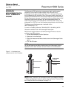
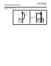
Distance calibration
1. Measure the actual distance between the Upper Reference Point and the
product surface.
2. Adjust the Calibration Distance so that the Distance measured by the
transmitter corresponds to the actual distance.
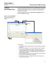
The Calibration Distance parameter is available via
HART command [2, 3, 2, 4, 1],
or
RRM:
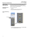
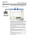
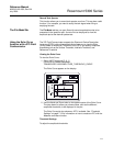
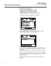
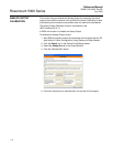
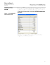
a. Click the Tank icon under Device Config/Setup in the RRM
workspace.
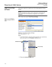
b. In the Tank window, select the Geometry tab.
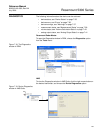
c. Click the Advanced button.
d. Enter the desired value in the Calibration Distance field and click
the Store button.
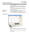
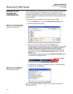
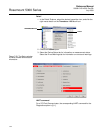
Level calibration
1. Measure the actual Product Level.
2. Adjust the Tank Height so the product level measured by the transmitter
corresponds to the actual product level.