


Reference Manual
00809-0100-4530, Rev BA
July 2009
Rosemount 5300 Series
7-14
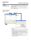
1. Select HART command [2, 5, 2].
F
OUNDATION Fieldbus parameter:
TRANSDUCER 1300>PROBE_END_THRESH
TRANSDUCER 1300>REFERENCE_THRESH
TRANSDUCER 1300>INTERFACE_THRESH
TRANSDUCER 1300>FULL_TANK_THRESH_OFFSET
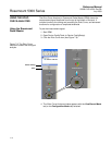
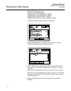
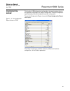
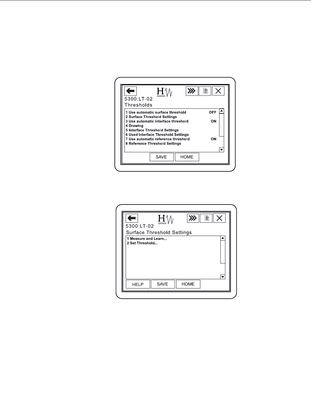
The different threshold options appear on the display:
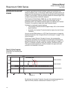
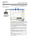
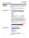
2. Open the desired option. For example, choosing option 2 Surface
Threshold Settings displays the following screen:
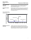
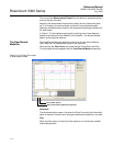
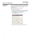
3. Option 1 Measure and Learn lets you create an Amplitude Threshold
Curve (ATC), see “Amplitude Threshold Curve” on page 7-7 for more
information.
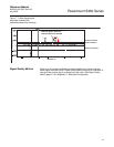
Option 2 Set Threshold lets you specify a constant Surface Threshold.
See also “Analyzing the Measurement Signal” on page 7-3 and “Surface
Pulse Not Found” on page 7-5 for more information on how to use the
amplitude thresholds.
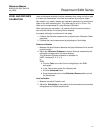
4. Click the SAVE button to store the new settings in the transmitter
database.