


5-42
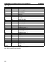
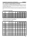
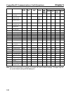
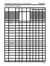
Constant Control mode settingChang
es dur-
ing op-
eration
Default
setting
Setting
range
Setting
unit
Regis-
ter No.
NameConstant
Flux
vector
Open
loop
vector
V/f with
PG
V/f
control
Chang
es dur-
ing op-
eration
Default
setting
Setting
range
Setting
unit
Regis-
ter No.
Name
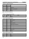
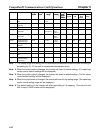
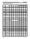
C5-06 ASR Primary delay
time
021A 0.001 0.000 to
0.500
0.004 No No No No Yes
C5-07 ASR Switching
frequency
021B 0.1 0.0 to 400.0 0.0 No No No No Yes
C5-08 ASR Integral (I) Limit 0241 1 0 to 400 400 No No No No Yes
C6-01 Carrier frequency
upper limit.
021C 0.1 2.0 to 25.0
(See note 4.)
15.0
(See
note 5.)
No Yes Yes Yes Yes
C6-02 Carrier frequency
lower limit.
021D 0.1 0.4 to 15.0 15.0
(See
note 5.)
No Yes Yes No No
C6-03 Carrier frequency
proportional gain.
021E 1 0 to 99 0 (See
note 5.)
No Yes Yes No No
C7-01 Hunting prevention
selection
021F 1 0, 1 1 No Yes Yes No No
C7-02 Hunting prevention
gain
022A 0.01 0.00 to 2.50 1.00 No Yes Yes No No
C8-08 AFR Gain 023A 0.01 0.00 to 10.00 1.00 No No No Yes No
C8-09 AFR primary delay
time
022B 1 0 to 2,000 50 No No No Yes No
C8-30 Carrier Frequency
Selection During
Auto-tuning
0240 1 0, 1 0 No No No Yes Yes
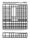
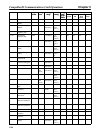
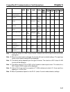
Note 1. The setting range and setting unit for acceleration/deceleration times will differ according to
the setting for C1-10 (the unit for acceleration/deceleration time).
Note 2. When the control mode is changed, the Inverter will revert to default settings. (The open loop
vector control default settings will be displayed.)
Note 3. When the control mode is changed, the Inverter will revert to default settings. (The flux vector
control default settings will be displayed.)
Note 4. When the control mode is changed, the Inverter will revert to the setting range. (The open loop
vector control setting range will be displayed.)
Note 5. The default setting of the Inverter will differ depending on its capacity. (The value for the
200-V-class 0.4 kW Inverter will be displayed.)
CompoBus/D Communications Card Operations Chapter 5