


5-25
5. Set up the Master Unit and 3G3FV Inverter connection by turning ON their power. The remote I/O
connection will then start up with the specified remote I/O operation.
When creating scan lists, set the scan list to disable mode once and then create scan lists or change
the settings as follows for the Inverter I/O allocation byte number from the Configurator.
S Basic/Standard remote I/O: 4 bytes (both for OUT and IN)
S Special remote I/O: 4 bytes (both for OUT and IN)
H Switching via Connection Objects
This method is defined by OVDA AC/DC drive objects.
Connection Objects for Switching Remote I/O Operations
To switch remote I/O operations by this method, the appropriate instance IDs must be set for the follow-
ing connection objects.
• Switching remote I/O inputs (3G3FV to SYSMAC PC):
Produced connection path (Class 05 hex, Instance 02 hex, Attribute 14 hex)
• Switching remote I/O outputs (SYSMAC PC to 3G3FV)
Consumed connection path (Class 05 hex, Instance 02 hex, Attribute 16 hex)
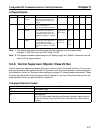
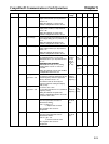
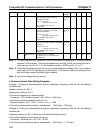
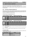
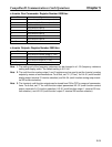
Remote I/O Instance ID
The instances to be set are shown in the following table.
Remote I/O type
Instance ID
Inputs (3G3FV to PC) Outputs (PC to 3G3FV)
Basic remote I/O 70 Dec (46 hex) 20 Dec (14 hex)
Standard remote I/O 71 Dec (47 hex) 21 Dec (15 hex)
Special remote I/O 150 Dec (96 hex) 100 Dec (64 hex)
Restrictions on Switching Remote I/O
To switch remote I/O operations, maintain either of the following conditions and send an explicit mes-
sage.
• Remote I/O communications stopped after the remote I/O connection and explicit message connec-
tion have been established.
• Remote I/O connection allocated after explicit message connection has been established.
Note The Configurator and OMRON Master Unit cannot create these conditions, so they cannot set
connection objects.
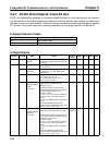
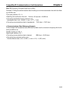
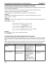
Data Setting Example
The set data must be converted to signal segments as defined by DeviceNet and then transferred. For
example, when remote I/O inputs are converted to special remote I/O inputs (instance ID: 96 hex), the
set data is as follows:
Instance ID set as ASCII code
“9” in ASCII code “6” in ASCII code
Number of subsequent bytes (2 bytes)
Header showing signal segment (011)
011000100011100100110110
777000
=62 39 36 Hex
CompoBus/D Communications Card Operations Chapter 5