


2-12
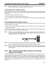
Basically, in the CompoBus/D Network the permissible maximum voltage drop within the system can be
specified at 5 V for a power supply line (+V or –V), by calculating the specifications for the voltage of the
communications power supply (24 VDC) and the input voltage of the communications power supply of
each device (11 to 25 VDC).
Of the permissible 5-V maximum voltage drop within the system, the permissible voltage drop is 4.65 V
in the trunk lines and 0.35 V in the drop lines.
The following formulae are applicable when power is supplied independently for communications
and the internal circuit. For details on voltage drop and formulae when the communications power
supply and internal circuit power supply are shared, refer to the CompoBus/D (DeviceNet) Opera-
tion Manual.
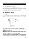
H Formulae
Try to calculate the best location for each node using the formula below. If the best location for each
node can be determined using the formula, the specifications for the power supply to each node can
also be met. Do not exceed the maximum current capacity of the cable (Thick Cable: 8 A and Thin
Cable: 3 A).
{(L
1
× R
C
+ N
1
× 0.005) × l
1
} + {(L
2
× R
C
+ N
2
× 0.005) × l
2
} + ..... + {(L
n
× R
C
+ N
n
× 0.005) × ln} x 4.65 V
Li: The distance (m) of the trunk line between the power supply and node i.
Rc: Maximum cable resistance for approx. 1 m
(Thick Cable: 0.015 Ω/m, Thin Cable: 0.069 Ω/m)
Ni: The number of T-branch Taps on the trunk line between the power supply and node i.
Ii: The consumption current required for the communications power supply for node i.
0.005 Ω = The contact resistance of the T-branch Taps.
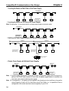
Note If there are nodes on both sides of the power supply, the formula is used to calculate the best
location in each direction, and if the conditions are satisfied, then the locations are valid. The
conditions are satisfied if the following equations are true.
Voltage drop (V) on trunk line at left side x 4.65 V
Voltage drop (V) on trunk line at right side x 4.65 V
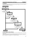
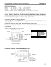
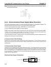
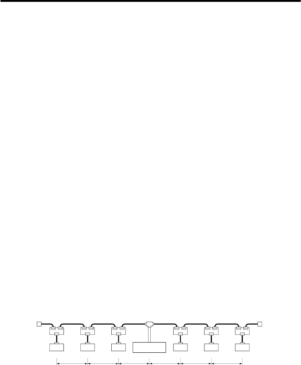
D Calculation Example
Communications
power supply
3 m
max.
0.25 A 0.2 A 0.15 A 0.25 A 0.15 A
Node Node Node Node Node
0.1 A
Node
Trunk line
(5-wire cable)
Terminating ResistorTerminating Resistor Trunk line
(5-wire cable)
40 m
40 m
40 m
40 m
40 m
40 m
Left Side Equation
Node 1: (120 0.015 + 3 0.005) 0.1 = 0.1815 (V)
Node 2: (80 0.015 + 2 0.005) 0.25 = 0.3025 (V)
Node 3: (40 0.015 + 1 0.005) 0.2 = 0.121 (V)
If 0.1815 + 0.3025 + 0.121 = 0.605 V x 4.65 V, the conditions are satisfied.
CompoBus/D Communications Line Design Chapter 2