


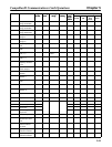
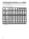

6-7
6-4 Inverter Faults
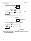
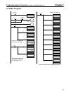
H Detecting Inverter Faults
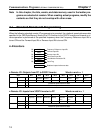
When a fault is detected in the Inverter itself, the status will change as shown in the following table.
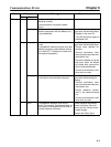
Function Inverter Fault Status
Remote I/O The fault output allocated in the remote I/O will turn ON.
If the fault output is ON, turn OFF all related inputs controlling the Inverter,
and program a sequence to stop the program.
Explicit messages Read the fault output for Class 29, Instance 1, Attribute 0A using message
communications. If there is a fault in the Inverter, the fault output will be ON,
so turn OFF all related inputs controlling the Inverter, and program a
sequence to stop the program.
Special remote I/O Read register 0010, and check whether bit 07 (fault output) is ON (serious
fault). If bit 07 is ON, turn OFF all related inputs controlling the Inverter, and
program a sequence to stop the program.
H Confirming Inverter Fault Status
The fault information for the Inverter can be checked by using the following methods. Perform trouble-
shooting based on the information corresponding to the fault and refer to maintenance information in
the SYSDRIVE 3G3FV High-function General-purpose Inverter User’s Manual (I516).
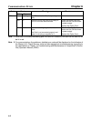
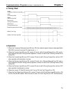
Function Inverter Error Status
Operation indicators on
Inverter
When there is an Inverter fault, the details will be displayed on the Digital
Operator of the Inverter. The fault log can be checked using the monitor
function (U3).
Explicit messages Read the fault code for Class 29, Instance 1, Attribute 0D using message
communications. The code corresponding to the Inverter fault is specified.
Special remote I/O Read registers 0014 to 0018. Check the fault status from the bit signals that
are output for an Inverter fault. The fault log can be checked using the
monitor function (U3) in registers 0090 to 0093.
H Memory Data Backup
The SYSDRIVE 3G3FV Inverter uses EEPROM for the data backup. Data is written to EEPROM when
the parameters change or the power is turned OFF.
• Data can be written to EEPROM up to 100,000 times.
• Parameters are always written to EEPROM when they are changed using CompoBus/D communica-
tions, so limit the times that parameters are written to EEPROM as much as possible.
(With the special I/O, data will be written to EEPROM when an enter command is received.)
• Frequency reference and control command (register numbers 0000 to 000F for the special I/O) and
the Net Control Bit and Net Reference Bit are not written to RAM or EEPROM. When the power is
turned OFF, any specified values are cleared.
Communications Errors Chapter 6