


7-6
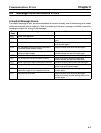
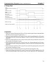
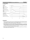
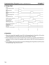
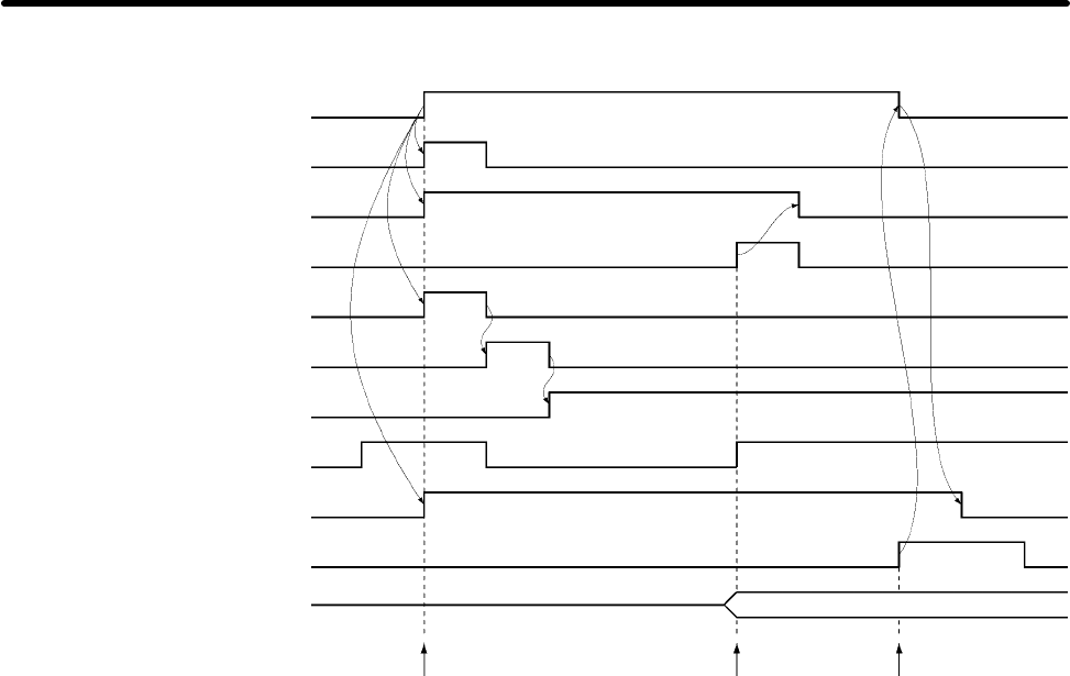
H Timing Chart
Word m bit 0
(Fault Bit)
00000
(Fault Read Flag)
03003
(Sending Message Flag)
03002
(Message Sent Flag)
IOWR instruction execution
00001
(IOWR Write Completed Flag)
00002
(Response Flag)
10112 (Message Communications
Enabled Flag)
03000 (Fault Flag)
00100 (Reset Input Bit)
DM0200 (Fault code storage) Fault code
1. 2. 3.
H Operation
1. When the Inverter has a fault, bit 0 of word m (Fault Bit) will be turned ON. Until the fault is cleared,
the Fault Flag will be turn ON, and this will cause the Fault Read Flag to be turned ON, and the com-
mand specified in the DM Area will be sent using the IOWR instruction.
2. When the Message Communications Enabled Flag is turned ON, the completion code (DM 2001)
will be examined. If an error is found, the error code will be stored in DM 0100 and re-send message.
If normally completed, the fault code will be stored in DM 0200 and the Message Sent Flag will be
turned ON, and the Sending Message Flag will be turned OFF.
3. When the Reset Input Bit is turned ON, bit 2 of word n (Fault Reset Input Bit) will turn ON. When the
fault is cleared, the Fault Flag will turn OFF.
Communications Programs (SYSMAC C200HX/HG/HE PCs) Chapter 7