


4-14
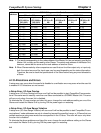
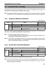
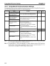
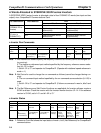
4-2-3 CompoBus/D Communications Settings
The parameters below have been added for functions that are exclusive to CompoBus/D communica-
tions. Set these parameters according to the desired application.
Constant
Name
Content Setting Default
Operator display
range setting
F9-01
Communications external
fault input selection
0: N.O. input (external fault detected when 1) 0, 1 0
CP-916 Setup
1: N.C. input (external fault detected when 0)
F9-02
Communications external
fault input detection
method selection
0: Fault detection during power ON
1: Fault detected during running only (when
0, 1 0
EF0 Detection
RUN commands are input)
F9-03
Communications external
fault input operation
selection
0: Decelerates to a stop using C1-02 decel-
eration time/fault detection
1: Coast to a stop/fault detection
2: Decelerates to a stop using C1-09 decel-
0 to 3 2
EF0 fault Action
eration time/fault detection
3: Continues operating/alarm detection (see
note 1)
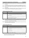
F9-04
Not used Do not set
0 to 0
F9-05 0 to 3 2
F9-06
CompoBus/D Fault op-
eration selection
0: Decelerates to a stop using C1-02 decel-
eration time/fault detection
1: Coast to a stop/fault detection
2: Decelerates to a stop using C1-09 decel-
0 to
3,300
0
BUS Fault Sel
eration time/fault detection
3: Continues operating/alarm detection (see
note 1)
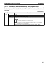
Note 1. If F9-03 or F9-06 is set to 3, the Inverter will continue operating. Be sure to install a limit switch
or an emergency stop switch as a safety precaution.
Note 2. The parameters for F9-06 are supported for Inverter software versions S1042 and later.
Check whether the parameter is applicable using the Inverter’s monitor function U1-14. In-
verters that do not support F9-06 will always coast to a stop.
CompoBus/D System Startup Chapter 4