


5-15
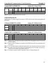
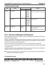
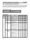
H Communications Flags
Type Name
Address
Content
Word Bit
SYSMAC
PC flags
Network Communications
Enabled Flag
A502 7: Port 7
6: Port 6
5: Port 5
4: Port 4
3: Port 3
2: Port 2
1: Port 1
0: Port 0
0: Execution disabled (executing)
1: Execution enabled (not executing)
Network Communications
Error Flag
A502 15: Port 7
14: Port 6
13: Port 5
12: Port 4
11: Port 3
10: Port 2
9: Port 1
8: Port 0
0: Normal end
1: Abnormal end
Master Unit
status flag
Message Communications
Enabled Flag
25 x Unit
number +
1501
12 0: Communications error detected;
Master Unit message communica-
tions not possible.
1: Master Unit communications pos-
sible.
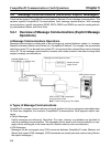
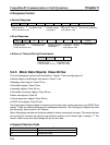
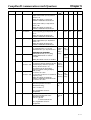
5-2-4 Overview of Messages and Responses
When message communications are used, the Inverter’s CompoBus/D Communications Card returns
responses as explained below.
Basically, CompoBus/D (DeviceNet) communications are executed in 1-byte (8-bit) units. In the case of
single-word data (16 bits), the rightmost bits (least significant) and the leftmost bits (most significant)
are reversed in order due to the following reasons:
• Data on communications line is transmitted in the order of rightmost bits and leftmost bits.
• Data that is internally processed by PC for issuing commands is transmitted in the order of leftmost bits
and rightmost bits.
Therefore, reverse the order for attributes where “Word” is written in the “Size” column in the tables on
subsequent pages and create attached data or read response data.
Note There is no need to take this into consideration for remote I/O because the rightmost bits and
leftmost bits are automatically reversed.
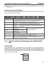
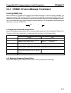
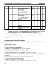
H Command Format
Command code
(FINS command for PC)
Destination
node address
Service data (attribute No. or at-
tribute No. and write data)
32 bytes max.
Service
code
Class ID
Instance ID
28 01
CompoBus/D Communications Card Operations Chapter 5