


1-12
Applicable PC C200HSC200HX/HG/HECV-series
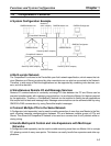
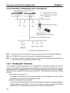
Allocation method Words are allocated to each node in the above data areas in any order
using the Configurator.
The following limitations apply:
The allocation areas are in 4 blocks (OUT 1, OUT 2, IN 1, and
IN 2). Each block consists of sequential words.
100 words max. per block.
For Slaves with more than 8 points, the first byte cannot be
specified in leftmost bits (7 to 15).
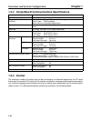
Words are allocated to Slaves as follows:
8-point Slaves: Allocated leftmost or rightmost byte of 1 word
16-point Slaves:Allocated 1 word
Slaves with more than 16-points: Allocated multiple words (For Slaves
with an odd number of bytes, the last byte will be the rightmost byte)
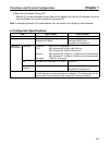
Max. No. of
Inverters
(using one
Without ex-
plicit mes-
sages
63 4 remote I/O words: 63
6 remote I/O words: 50
4 words remote I/O: 20
6 words remote I/O: 13
Master Unit
only)
With explicit
messages
63 4 remote I/O words: 25
6 remote I/O words: 16
---
Max. No. Inverters with more
than one Master Unit
Calculate from the number of words allocated in the data areas and the
number of words allocated to the Inverters (4 or 6 words).
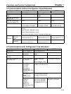
Note 1. The DM Area cannot be manipulated by bit, so it cannot be allo-
cated for remote I/O for Inverters.
Note 2. If the CPU Bus Link is used with a CV-series PC, the CPU Bus
Link Area will be used for the CPU Bus Link Therefore, the CPU
Bus Link Area cannot be allocated to Inverters if the CPU Bus
Link is used.
Functions and System Configuration Chapter 1