


!
!
!
!
!
!
3-5
3-2 Installation and Wiring
WARNING Never touch any internal parts of the Inverter. Doing so may result in electric shock.
WARNING Install, remove, or wire the Optional Card only after turning OFF the Inverter, making
sure that all the indicators of the Inverter are OFF, and waiting for the time specified
on the front cover of the Inverter to elapse. Not doing so may result in electric shock.
WARNING Do not damage, press, or put excessive stress or heavy objects on the cables. Doing
so may result in electric shock, product malfunction, or product damage.
Caution Do not touch the parts of the Optional Card by hand. Otherwise, static electricity may
damage the Optional Card.
Caution Be sure that the connector of the Optional Card is firmly in place on the Inverter. Im-
proper connection may cause injury, product malfunction, or product damage.
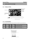
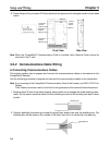
3-2-1 CompoBus/D Communications Card Installation
Caution Before installing and wiring an Optional Card, always turn OFF the power to the
SYSDRIVE 3G3FV Inverter and wait for the CHARGE indicator to turn OFF.
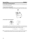
H Mounting Procedure
1. Turn OFF the Inverter, wait for at least one minute (or at least three minutes if the Inverter has an
output capacity of 30 kW or more), remove the front cover of the Inverter, and check that the
CHARGE indicator is not lit.
2. Mount the Optional Card to the option C area.
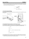
3. Insert the provided spacers into the spacer holes on the mounting base of the Inverter.
4. After properly engaging the connectors of the Optional Card and control circuit board, insert the
spacers to the spacer holes of the Optional Card, and press the Optional Card until the spacers
click.
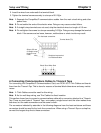
5. Connect the shielded ground cable of the Optional Card to FG terminal 12 (E) on the control circuit
board of the Inverter.
Setup and Wiring Chapter 3