


2-6
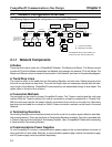
2-3 Communications Power Supply
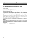
2-3-1 Locating the Communications Power Supply
H Basic Concept
• The communications power supply must be 24 VDC.
• Make sure that the power is supplied from the trunk line.
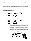
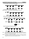
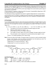
• When providing power to several nodes from one power supply, if possible try to locate the nodes in
both directions from the power supply.
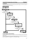
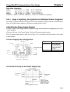
• Provide power through Power Supply Taps. It is, however, possible to use T-branch Taps instead when
there is one communications power supply in the system and the total current consumption is less
than 5 A.
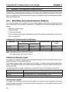
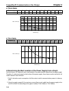
• The power supply capacity for cables is restricted to 8 A for Thick Cables and 3 A for Thin Cables.
• A single Network is usually supplied by one power supply. It is, however, possible to have more than
one power supply when power supply specifications cannot be met with a single power supply. (See
2-3-4 Step 3: Splitting the System into Multiple Power Supplies.)
• Fully consider the power supply capacity allowance in the design.
• If the power supply is switched OFF during the operation of the Network, there may be a malfunction in
the nodes.
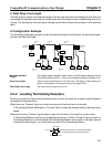
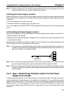
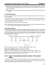
• The current capacity of the drop line varies according to its length. The longer the drop line, the lower
its maximum capacity becomes. This is the same whether the cable is thick or thin. Calculate the cur-
rent capacity passing through the drop line I (the total current consumption at the drop line) using the
following formula.
I = 4.57/L I: Permissible current (A)
L: Length of the drop line (m)
CompoBus/D Communications Line Design Chapter 2