


7-15
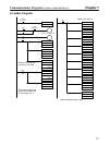
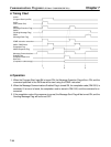
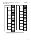
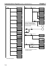
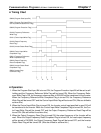
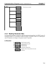
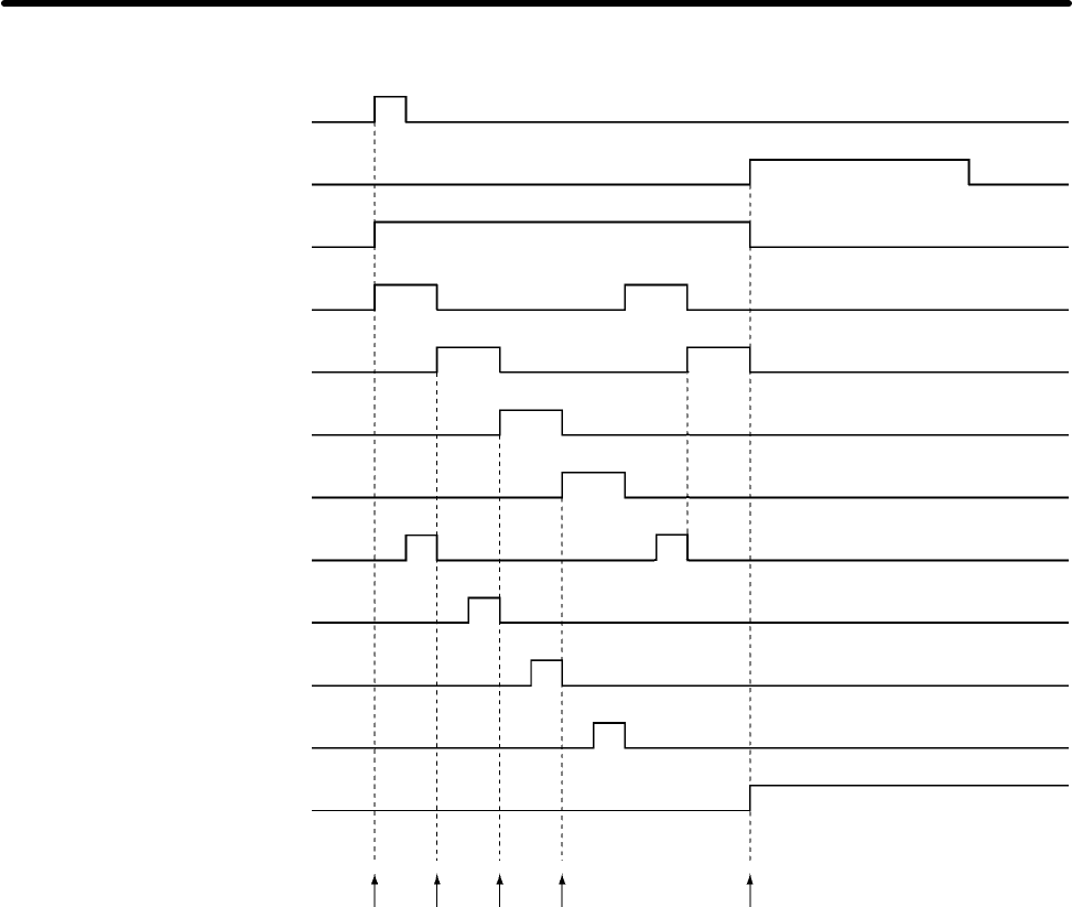
H Timing Chart
00000 (Program Start Input Bit)
00001 (Program End Input Bit) or
03110 (Communications Error Flag)
00002 (Program Execution Flag)
00100 (Frequency Reference
Write Flag)
00101 (Control Input Write Flag)
00102 (Output Frequency
Read Flag)
00103 (Inverter Status Read Flag)
00300 (Control Input Write
Completed Flag)
00301 (Frequency Reference
Write Completed Flag)
00302 (Output Frequency
Read Completed Flag)
00303 (Inverter Status Read
Completed Flag)
00004 (Inverter Stop
Command Flag)
1. 2. 3. 4. 5.
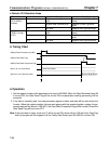
H Operation
1. When the Program Start Input Bit is turned ON, the Program Execution Input Bit will be set to self-
holding and the Frequency Reference Write Flag will be turned ON. When the Frequency Refer-
ence Write Flag is ON, the frequency reference data in DM1000 will be transferred to the Inverter.
When the Frequency Reference Write Completed Flag is turned ON, the Frequency Reference
Write Flag will be turned OFF and the Control Input Write Flag will be turned ON. (Bits are shifted to
achieve this.)
2. When the Control Input Write Flag is turned ON, the Inverter control input specified in word 010 will
be transferred to the Inverter. When the Control Input Write Completed Flag is turned ON, the Con-
trol Input Write Flag will be turned OFF and the Output Frequency Reference Read Flag will be
turned ON. (Bits are shifted to achieve this.)
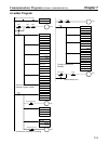
3. When the Output Frequency Read Flag is turned ON, the output frequency of the Inverter will be
read. When the Output Frequency Read Completed Flag is turned ON, the read output frequency
will be stored in DM 2000, the Output Frequency Read Flag will be turned OFF, and the Inverter
Status Read Flag will be turned ON. (Bits are shifted to achieve this.)
Communications Programs (SYSMAC C200HX/HG/HE PCs) Chapter 7