


7-20
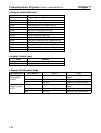
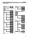
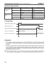
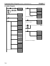
D Remote I/O Allocation Areas
I/O classification Word 15 to 8 7 to 0
Output
(PC to 3G3FV
n Register number (leftmost
byte)
Function code (10: Write, 03:
Read)
Inverter)
n+1 Register data (leftmost byte) Register number (rightmost
byte)
n+2 Not used. Register data (rightmost byte)
Input
(3G3FV Inverter
m Register number (leftmost
byte)
Function code (10: Write, 03:
Read)
to PC)
m+1 Register data (leftmost byte) Register number (rightmost
byte)
m+2 Not used. Register data (rightmost byte)
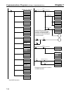
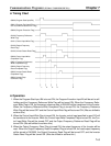
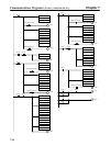
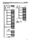
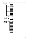
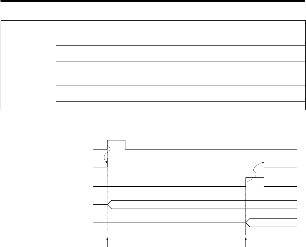
H Timing Chart
Receive Data (Read)
1. 2.
Send Data (Read)
03000 (Data Read Flag)
Word n to n+2 (Send Data)
Word m to m+2 (Receive Data)
00000 (Read Parameter Input Bit)
03005 (Data Read Completed Flag)
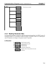
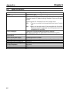
H Operation
1. Set the register number of the parameter to be read in DM 0000. When the Read Parameter Input Bit
is turned ON, the Data Read Flag will be turned ON and parameter reading processing will be
executed.
2. If the data is normally read, the read parameter register number and data will be returned by the
Inverter. When the register number that was sent agrees with the received register number, the pa-
rameter data will be stored in DM 0001, the Data Read Completed Flag will be turned ON and the
Data Read Flag will be turned OFF.
Note If the send data is faulty, word m bit 7 will be turned ON, which will turn ON the Faulty Data Flag
and the program will be stopped until the Faulty Data Reset Input Bit (00002) is turned ON.
Communications Programs (SYSMAC C200HX/HG/HE PCs) Chapter 7