


5-30
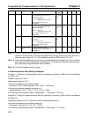
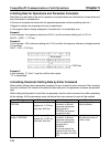
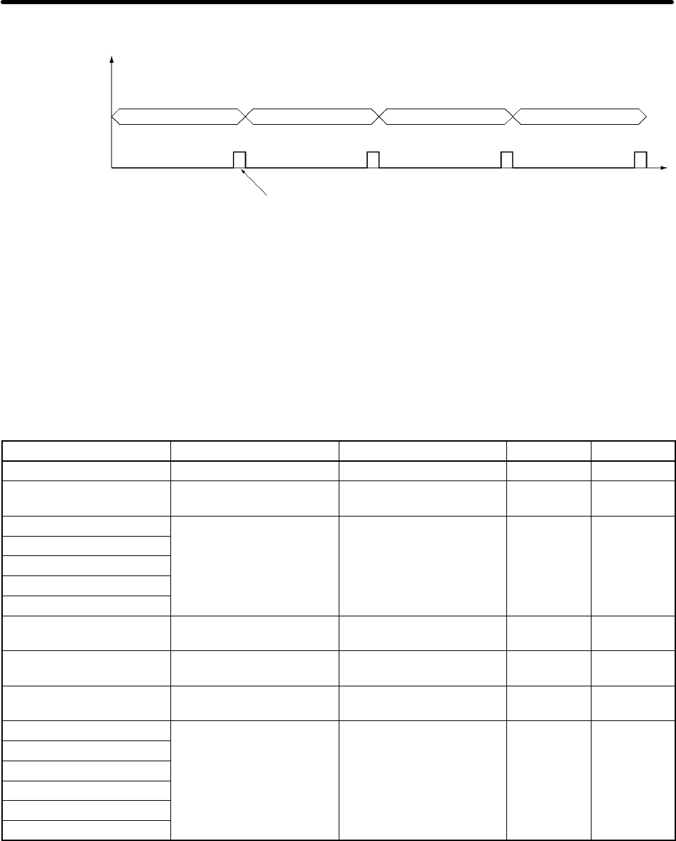
H Handling Illustration
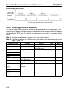
Function code
register number
Processing
contents
10 hex
0001 hex
10 hex
0000 hex
03 hex
0021 hex
03 hex
0010 hex
Frequency reference writing
Inverter run command writing
Output frequency monitoring Inverter status reading
Transmission
completed signal
Function code–response number comparison (CMP)
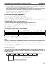
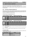
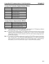
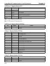
5-4-3 Inputting Control/Frequency
The Inverter’s various control inputs are allocated to the registers shown in the following table. For ex-
ample, to set the frequency reference and begin operation, first set the reference value to the frequency
reference register “0001,” and then write the run command to the Inverter’s run command register
“0000.”
Note 1. Set values are retained until changed by the next writing operation.
Note 2. The following registers are in RAM, so they are all cleared to zero when the Inverter’s power
supply is turned OFF.
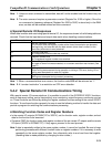
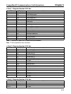
Register No. (hex) Function Content Read Write
0000 Inverter run command (Refer to table below.) Yes Yes
0001 Frequency reference Sets frequency reference
value. (See note 1.)
Yes Yes
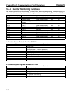
0002
Not used.
0003
0004
0005
0006
0007 Multi-function analog out-
put 1 (See note 2.)
+11 V = 02D6 hex Yes Yes
0008 Multi-function analog out-
put 2 (See note 2.)
+11 V = 02D6 hex Yes Yes
0009 Inverter output (See note
3.)
(Refer to table below.) Yes Yes
000A
Not used.
000B
000C
000D
000E
000F
CompoBus/D Communications Card Operations Chapter 5