


4-11
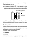
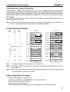
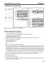
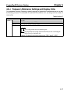
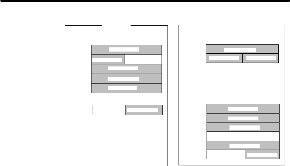
H Example of Free Allocations
Output area
CIO 1950
CIO 1951
CIO 1952
CIO 1953
CIO 1954
CIO 2000
Allocated (01)
Not used
Not used
Allocated (12)
Allocated (02)
Allocated (10)
Allocated (10)
Allocated (02)
Allocated (01)
Allocated (00)
CIO 1900
CIO 1901
Allocated (03)
Allocated (04)
Allocated (04)
Allocated (04)
Allocated (12)
Allocated (09)
Not used
Not used
Input area
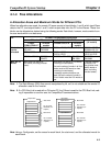
Output block 1
Input block 2
Output block 2
Input block 1
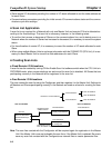
Node
address
Output
points
Input
points
0
1
2
3
10
16
8
16
0
32
0
8
16
8
0
Node
address
4
9
12
0
0
8
48
8
16
Input
points
Output
points
CIO 0010
CIO 0011
CIO 0012
CIO 0013
CIO 0014
CIO 0015
Note The above example is for a CV-series PC.
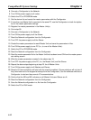
H Basic Application Procedure
1. Set the initial settings for the Master Unit:
Unit number (“UNIT No.” or “MACHINE No.” on front panel switch)
Node address (back panel DIP switch)
Baud rate (front panel DIP switch)
Communications continue/stop setting for communications error (front panel switch)
2. Set the initial settings for the Slaves:
Node address (DIP switch)
Baud rate (DIP switch)
Etc.
3. Mount the Master Unit and wire the Network.
For CV-series PCs, Master Units are treated as CPU Bus Units and can be mounted to the CPU
Rack or Expansion CPU Rack. Up to 16 Master Units can be mounted if a Configurator is used.
For C200HX/HG/HE PCs, Masters are treated as Special I/O Units and can be mounted to the CPU
Rack or Expansion I/O Rack. Up to 10 or 16 Master Units can be mounted if a Configurator is used.
For C200HS PCs, Masters are treated as Special I/O Units and can be mounted to the CPU Rack or
Expansion I/O Rack. Up to 10 or 16 Master Units can be mounted if a Configurator is used.
4. Connect a Programming Device to the PC and turn ON the power supply to the PC.
5. Generate the I/O table.
6. Turn OFF the power to the PC.
7. Go to step 8. if only one Master Unit is being used and to step 15. if more than one Master Unit is
being used in the same Network.
CompoBus/D System Startup Chapter 4