


5-32
5-4-4 Inverter Monitoring Functions
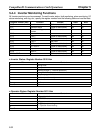
All Inverter monitoring can be accessed. To read Inverter status, fault monitoring, alarm monitoring, I/O
status monitoring, error log, etc., specify the register number from the following table and read the data.
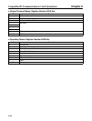
Register number (hex) Function Content Read Write
0010 Inverter status (Refer to table below.) Yes No
0011 Operator status (Refer to table below.) Yes No
0012 Operator setting error
number
OPE error number Yes No
0013 Not used.
0014 Fault 1 (Refer to table below.) Yes No
0015 Fault 2 (Refer to table below.) Yes No
0016 Fault 3 Not used. Yes No
0017 CPF error 1 (Refer to table below.) Yes No
0018 CPF error 2 (Refer to table below.) Yes No
0019 Alarm 1 (Refer to table below.) Yes No
001A Alarm 2 (Refer to table below.) Yes No
001B to 001F Not used. (Refer to table below.)
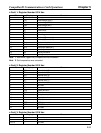
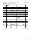
D Inverter Status: Register Number 0010 Hex
Bit Content
0 During RUN
1 Zero speed
2 Forward/reverse (1: Reverse operation)
3 During Fault Reset input
4 Frequency agree 1
5 Inverter operation ready
6 Alarm
7 Fault
8 to 15 Not used.
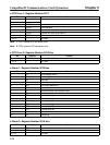
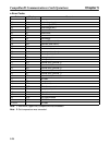
D Operator Status: Register Number 0011 Hex
Bit Content
0 1: Operation fault
1 1: EEPROM error
2 1: Program mode
3
00: Operator connecting
4
11: Operator disconnecting
5 to 15 Not used.
CompoBus/D Communications Card Operations Chapter 5