


2-10
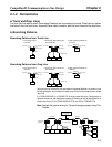
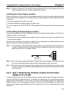
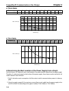
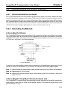
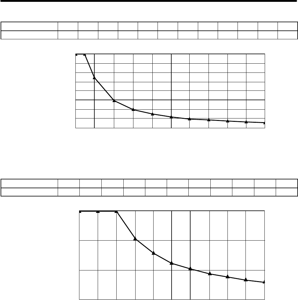
H Thick Cable
Distance (m) 0 25 50 100 150 200 250 300 350 400 450 500
Max. current (A) 8.00 8.00 5.42 2.93 2.01 1.53 1.23 1.03 0.89 0.78 0.69 0.63
Max. current (A)
Distance (m)
8
7
6
5
4
3
2
1
0
0
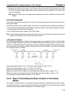
H Thin Cable
Distance (m) 0 10 20 30 40 50 60 70 80 90 100
Max. current (A) 3.00 3.00 3.00 2.06 1.57 1.26 1.06 0.91 0.80 0.71 0.64
Max. current (A)
Distance (m)
3
2
1
0
0
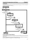
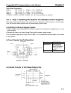
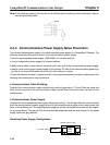
H Determining the Best Location of the Power Supply from a Graph
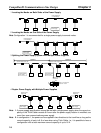
Verify the Items 1 to 3 below for each node located in the same direction viewed from the power supply.
Therefore, if nodes are located on both sides of the power supply, these items must be verified for all
nodes located in each direction.
1 Find A, the total current consumption of all the nodes to which communications power is to be sup-
plied.
2 Using the graph compute B, the maximum current flow in each cable from the power supply to the
end of the trunk line according to the types of cables (Thick Cables or Thin Cables).
CompoBus/D Communications Line Design Chapter 2