


5-35
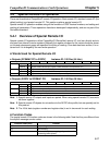
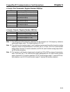
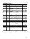
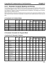
H Inverter Monitoring: U1–jj
Register
number
Monitor
number
Monitored item Output unit Read Write
0020 U1-01 Frequency reference Set in o1-03 Yes No
0021 U1-02 Output frequency Set in o1-03 Yes No
0022 U1-03 Output current 8192 dec = Inverter rated
current
Yes No
0023 U1-04 Control method Set in A1-02 Yes No
0024 U1-05 Motor speed Set in o1-03 Yes No
0025 U1-06 Output voltage 0.1 V Yes No
0026 U1-07 Main circuit DC voltage 1 V Yes No
0027 U1-08 Output power 0.1 kW Yes No
0028 U1-09 Torque reference 0.1% Yes No
0029 U1-10 Input terminal status Bits 0 to 7 = terminals 1 to
8
Yes No
002A U1-11 Output terminal status (Refer to table below.) Yes No
002B U1-12 Operating status (Refer to table below.) Yes No
002C U1-13 Elapsed time 1 hour Yes No
002D U1-14 FLASH ID software No. --- Yes No
002E U1-15 Terminal 13 level 0.1% (100% = 10 V) Yes No
002F U1-16 Terminal 14 level 0.1% (100% = 20 mA) Yes No
0030 U1-17 Terminal 16 level 0.1% (100% = 10 V) Yes No
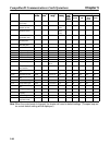
0031 U1-18 Motor secondary current 0.1% (100%: Motor rated
current)
Yes No
0032 U1-19 Motor excitation current 0.1% (100%: Motor rated
current)
Yes No
0033 U1-20 Output frequency after a
soft start
Set in o1-03 Yes No
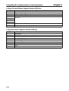
0034 U1-21 Input to speed control loop 0.01% (100%: Maximum
frequency)
Yes No
0035 U1-22 Output from speed control
loop
0.1% (100%: Motor rated
current)
Yes No
0036 U1-23 Speed deviation 0.01% (100%: Maximum
frequency)
Yes No
0037 U1-24 PID feedback 0.01% (100%: Maximum
frequency)
Yes No
0039 U1-26 Voltage reference for
secondary current
0.1 V Yes No
003A U1-27 Voltage reference for
excitation current
0.1 V Yes No
003B U1-28 CPU ID --- Yes No
CompoBus/D Communications Card Operations Chapter 5