


2-7
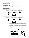
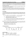
H Flowchart
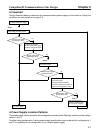
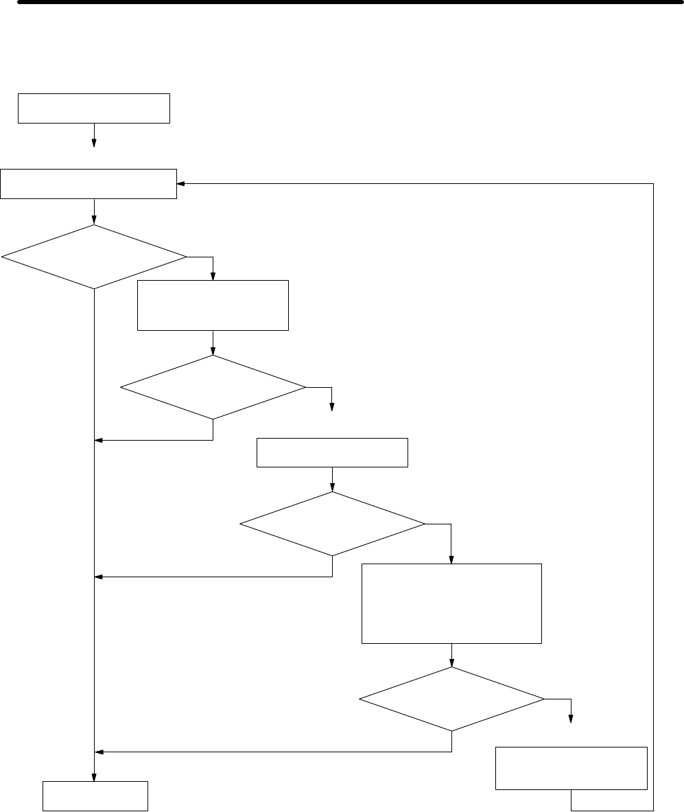
Use the flowchart below to determine the communications power supply on the trunk line. Satisfy the
conditions for each drop line on page 2-6.
Provisionally determine the
location of the power supply.
Step 1
Are the power supply
specifications met?
Step 2
Determine the best location of the
power supply from the graphs.
Are the power supply
specifications met?
Calculate the best location
of the actual nodes.
Consider changing the
location of the power supply.
Consider using Thick Cable.
Are the power supply
specifications met?
Consider changing the location of
the power supply.
Consider using Thick Cable.
Consider changing the location of
high current consumption nodes.
Set the location for
the power supply.
Split the power supply
system by installing more
than two power supplies.
No
Yes
Yes
No
No
Are the power supply
specifications met?
No
Step 3
Yes
Yes
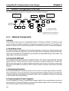
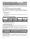
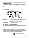
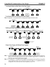
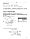
H Power Supply Location Patterns
The power supply can be located in the configurations shown below. Basically, select from the configu-
rations 1 and 2.
Consider using configuration 3 when power supply specifications cannot be met by configurations 1
and 2. It is possible to use configuration 4 for a duplex power supply.
CompoBus/D Communications Line Design Chapter 2