


4-13
4-2 SYSDRIVE 3G3FV Settings
Set the parameters according to the applications of the Inverter for CompoBus/D communications. The
shaded part in the following table indicates the default setting.
Note The parameters set here are applied to the CompoBus/D Communications Card when the power
is turned ON. Turn OFF the power after changing parameters and turn ON again to apply them.
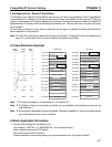
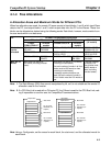
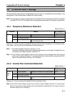
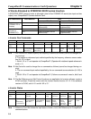
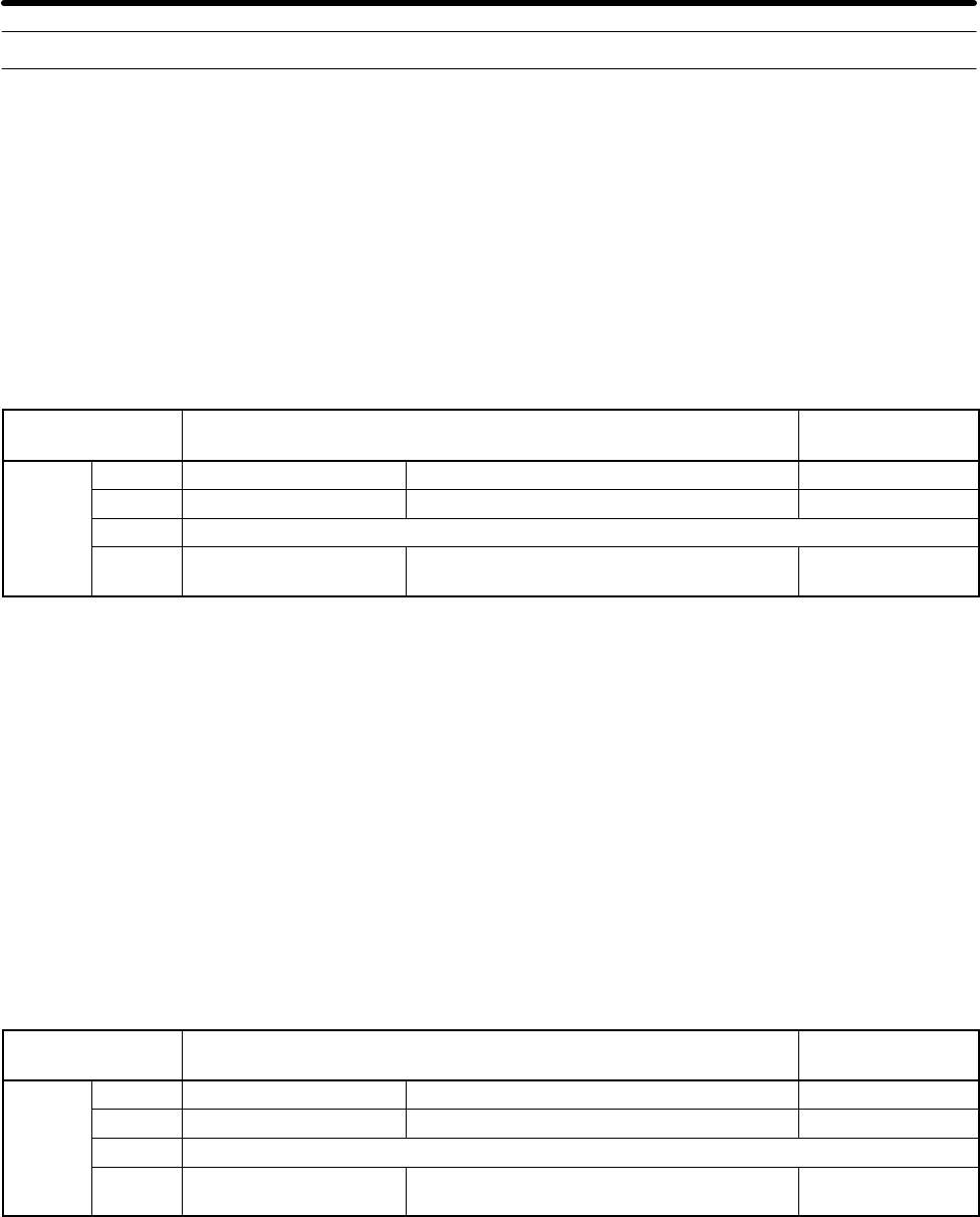
4-2-1 Frequency Reference Selection
Default setting: 1
Constant Content REF indicator of
Digital Operator
B1-01
0 D1-01 Frequency reference from D1-01 Not lit
1 External terminals Frequency reference from external input Lit
2 Do not set (not used)
3 Optional Card Frequency reference from CompoBus/D
Communications Card
Lit
Always set “3” when using the CompoBus/D Communications Card. By setting “3,” the frequency refer-
ence value 1 can be set only by CompoBus/D communications.
Note 1. This setting enables frequency reference 1 only.
Frequency reference can be set for frequency references 2 to 8 through CompoBus/D com-
munications and Digital Operator without B1-01.
Note 2. If the S1042 or later software version of the Inverter is used, settings other than 3 can be
made, and Frequency Reference 1 can be switched with communications using the Net. Ref.
signal. (Communications setting or b1-03 setting.)
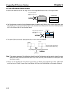
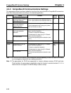
4-2-2 Inverter Run Command Selection
Default setting: 1
Constant Content SEQ indicator of
Digital Operator
B1-02
0 Digital Operator Operation command from Digital Operator Not lit
Run
1 External terminals Operation command from external input Lit
Source
2 Do not set (not used)
Sel.
3 Communications Operation command through communica-
tions
Lit
Always set “3” when using the CompoBus/D Communications Card.
Note If the S1042 or later software version of the Inverter is used, settings other than “3” can be made,
and Run Command can be switched with communications using the Net. Ctrl. signal. (Commu-
nications setting or b1-03 setting.)
CompoBus/D System Startup Chapter 4