


2-15
2-4 Communications Line Noise Prevention
2-4-1 Communications Line Noise
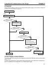
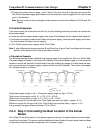
The communications line sends and receives high-speed pulse signals, and checks whether the data is
correct by checking the sequence of the signals. If the amount of noise on the communications line is too
great, the interference will alter the communications signal data, and communications will be impossi-
ble. Communications lines are more sensitive and require higher speeds than normal I/O lines, so be
sure that noise does not interfere with communications. Use the preventative noise countermeasures
described here when configuring the system to ensure smooth system start up.
2-4-2 Grounding the Network
H Grounding the Network
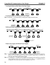
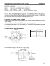
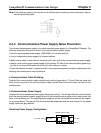
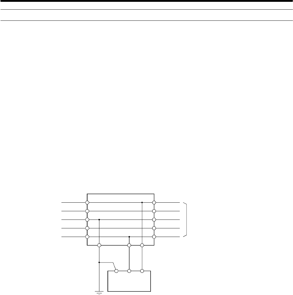
The CompoBus/D Network must be grounded at only one location so that a ground loop is not created.
The ground should also be connected as close as possible to the center of the Network. Connect the
cable shield to the ground terminal on the communications power supply and then connect to a ground
of 100 Ω max., as shown in the following diagram.
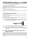
Power Supply Tap
V+
CAN H
CAN L
Shield
V+
CAN H
CAN L
Shield
Communications
cable
V+
V+
V–
V–FG
Communications
power supply
Ground
terminal
V–
V–
Ground (100 Ω max.)
If more than one communications power supply is connected to the same Network, ground only the one
nearest the center of the Network. Do not connect the shield wire at the other power supplies.
Note 1. Always ground the communications cable shield at one and only one location in the Network.
Note 2. Always ground to 100 Ω or less.
Note 3. Always use a separate ground. Never use the same ground as for Inverters or other drive
system devices.
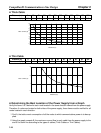
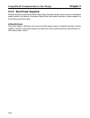
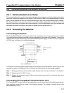
H Grounding the CompoBus/D Communications Card
The CompoBus/D Communications Card should be grounded according to DeviceNet recommenda-
tions installing a noise filter as shown in the following diagram. The ground is normally wired to the
ground terminal (12 (G)).
CompoBus/D Communications Line Design Chapter 2