


2-9
Note 3. Consider changing to Thick Cable to meet specifications if the current capacity of the Thin
Cable exceeds 3 A when using Thin Cable for the trunk line.
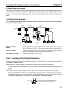
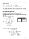
H Setting the Power Supply Location
Determine whether or not the current can be supplied normally by finding the current capacity required
by each node and the voltage drop in the cables to be used to provide power. Calculate the values below
in advance.
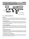
• The current capacity required by each node
• The distance between the power supply and each node
The current capacity of the 3G3FV-PDRT1-SIN CompoBus/D Communications Card is approximately
20 mA.
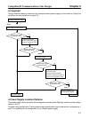
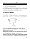
H Calculating the Power Supply Location
There are two methods to find the best location of the communications power supply on the trunk line.
• Simple calculation from a graph
• Calculation by formula (Calculating the voltage drop from resistance and current consumption of the
communications cables).
Each drop line must satisfy the equation on page 2-6, which represents the relationship between the
drop line length and the current capacity for the drop line.
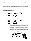
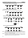
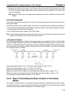
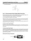
Note 1. From the graph, a hypothetical power supply location can be determined if the conditions cal-
culated in the graph are met by estimating the worst configuration (that has the maximum volt-
age drop as shown in the diagram below).
Communications
power supply
Node
Node
Node
Node
Note 2. Even if the power supply specifications cannot be met using the graph, the conditions can be
met and a hypothetical power supply location determined by using the formula.
Note 3. When the communications power supply and the internal circuit supply are the same, use the
formula to calculate a hypothetical power supply location because it cannot be determined by
using the graph.
2-3-2 Step 1: Determining the Best Location for the Power
Supply from a Graph
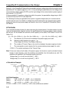
A voltage drop occurs when a current flows through a communications cable. The longer the commu-
nications cable and the larger the current, the greater the voltage drop. The communications power
supply at each node must be 11 VDC or more. To ensure the correct power supply, the relationship is
plotted as shown in the following graph to find the maximum current that satisfies the voltage of the
communications power supply at different trunk line lengths even if there is a voltage drop due to cable
resistance.
CompoBus/D Communications Line Design Chapter 2