


2-13
Right Side Calculation
Node 4: (40 0.015 + 1 0.005) 0.15 = 0.09075 (V)
Node 5: (80 0.015 + 2 0.005) 0.25 = 0.3025 (V)
Node 6: (120 0.015 + 3 0.005) 0.15 = 0.27225 (V)
If 0.09075 + 0.3025 + 0.27225 = 0.6655 V x 4.65 V, the conditions are satisfied.
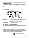
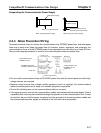
2-3-4 Step 3: Splitting the System into Multiple Power Supplies
Go to Step 3 if the best location for the nodes cannot be calculated from the formulae. In the third step,
there are multiple power supplies and the power supply system is split.
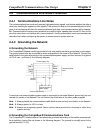
H Splitting the Power Supply System
• Be sure to use a Power Supply Tap for each power supply when the Network is supplied by two or more
power supplies.
• Remove the fuses in the Power Supply Tap to split the power supply system.
Once the power supply system is split, return to Step 1 or 2, and determine the best location of the nodes
in each system.
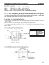
H Power Supply Tap Configuration
Model 1485T-R2T5-T5
Specification Power supply tap
(with a grounding
terminal and reverse
current prevention
function )
Manufacturer Allen-Bradley
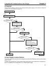
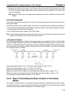
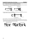
H Internal Circuitry of the Power Supply Tap
V+
Power Supply Tap
5-wire cables
on side B
Schottky
diode
Fuses used:
Littel fuse 312008
Rated amperage: 8 A
Rated voltage: 250 V
6.35 Φ x 31.75 mm
Ground
terminal
Power supply device on side C
V+
CAN H
Shield
CAN L
V–
V–
Fuse A Fuse B
V+
CAN H
Shield
CAN L
V–
5-wire cables
on side A
CompoBus/D Communications Line Design Chapter 2
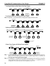
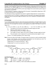
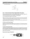
Connector C
Fuse A
Cable A
Power supply cable
Fuse B
Connector B
Cable B
Connector A