


7-3
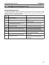
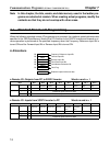
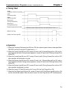
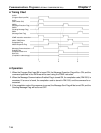
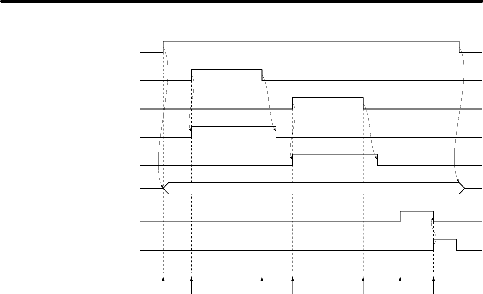
H Timing Chart
00000
(Frequency Reference Input Bit)
00001
(Forward Input Bit)
00002
(Reverse Input Bit)
Word m bit 2
(During Forward Run)
Word m bit 3
(During Reverse Run)
Rotational speed reference data
DM 0000 (rotational speed reference data transmitted to words n + 1)
03000 (Fault Flag)
00003 (Fault Reset Input Bit)
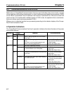
1.
2.
3.
4.
5.
6.
7.
H Operation
1. When the Frequency Reference Input Bit turns ON, the rotational speed reference data specified in
DM 0000 is moved to remote I/O output word n + 1.
2. When the Forward Input Bit turns ON, remote I/O word n bit 0 (Forward/Stop) will turn ON, and for-
ward operation will start. During forward operation, remote I/O word m bit 2 (During Forward Run)
will be ON.
3. When the Forward Input Bit turns OFF, remote I/O word m bit 2 (During Forward Run) will turn OFF
after operation will decelerate to a stop.
4. When the Reverse Input Bit turns ON, remote I/O word n bit 1 (Reverse/Stop) will turn ON, and re-
verse operation will start. During reverse operation, remote I/O word m bit 3 (During Reverse Run)
will be ON.
5. When the Reverse Input Bit turns OFF, remote I/O word m bit 3 (During Reverse Run) will turn OFF
after operation decelerates to a stop.
6. When the remote I/O Fault Bit (word m bit 0) turns ON, the Fault Flag will turn ON.
7. When the Fault Reset Input Bit turns ON, remote I/O word n bit 2 (Fault Reset Input Bit) will turn ON,
and the fault will be cleared. When the fault is reset, the Fault Flag will turn OFF simultaneously.
Communications Programs (SYSMAC C200HX/HG/HE PCs) Chapter 7