


6-2
6-1 Communications Line Errors
Malfunctions in CompoBus/D communications that are a result of broken wires, short circuits, reversed
wiring, duplicate node address assignments, or noise interference are detected as transmission (BUS)
errors. When a transmission error is detected, the Inverter’s Fault Bit will turn ON and the motor will
coast to a stop. (For Inverters with a software version of 1042 or later, the operation when a communica-
tions error occurs can be set using constant F9-06.)
When an error is detected, perform error processing according to the indicator display of the Compo-
Bus/D Communications Card.
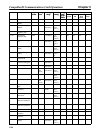
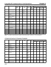
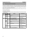
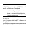
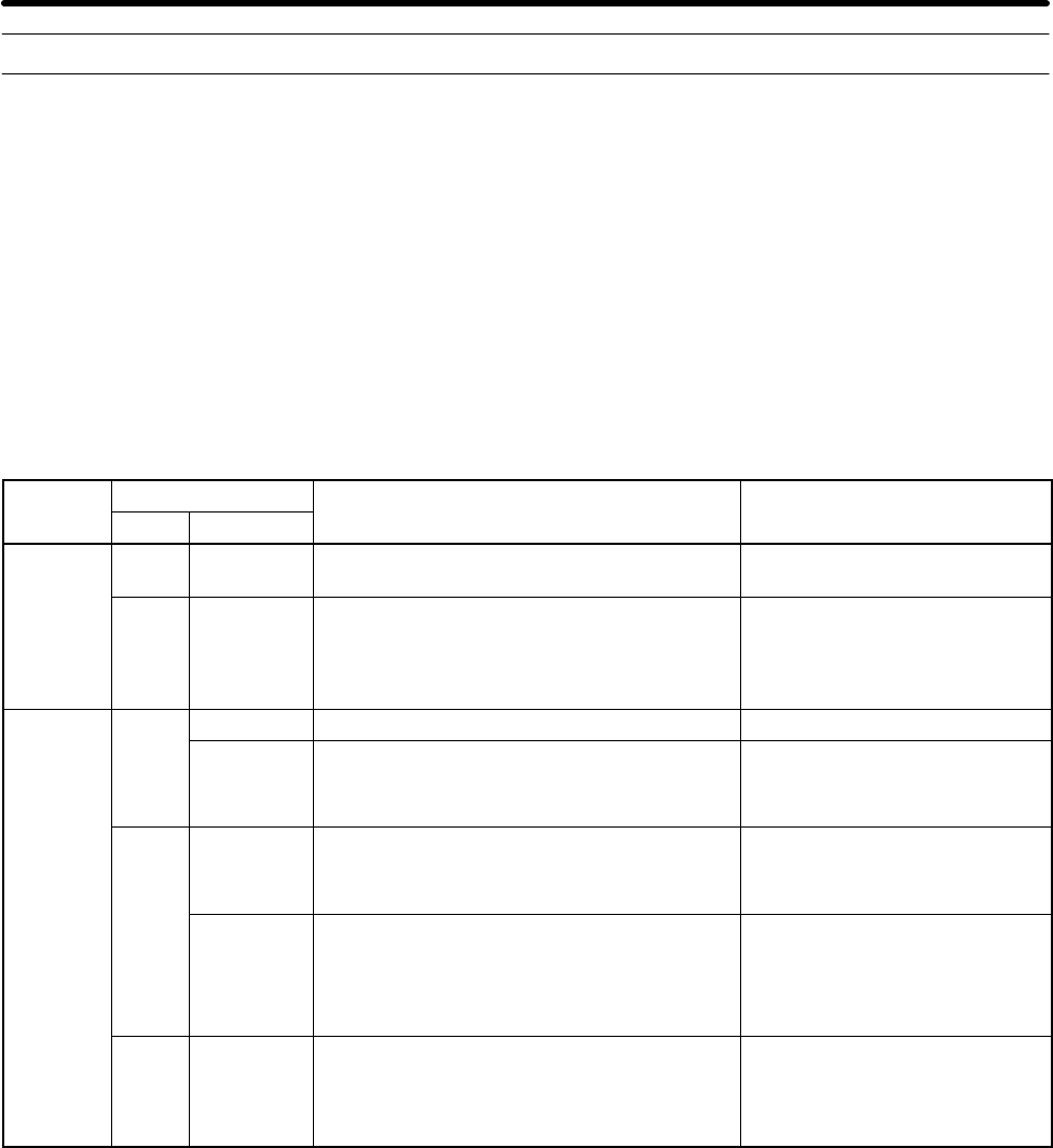
H Operation Indicators
The CompoBus/D Communications Card has 4 operation indicators that show the status of the power
and communications.
Indicator
Display
Meaning Countermeasures
Color Status
PWR
Green Lit Power is being supplied from the Inverter
to the Card.
---
--- Not lit Power is not being supplied from the In-
verter.
The Card is not connected properly and
power is not being supplied to it.
Check the Option Card con-
nector and turn ON the Invert-
er power supply.
Replace the Option Card.
MS Green
Lit The Card is operating normally. ---
Flashing Initial settings or necessary preparations
for communications are incomplete.
Turn ON the Inverter power
supply again.
Replace the Option Card.
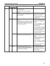
Red
Lit A fatal error (hardware error) has occurred
in the Card.
Turn ON the Inverter power
supply again.
Replace the Option Card.
Flashing A non-fatal error, such as a switch setting
error, has occurred.
Check the baud rate setting.
Turn ON the Inverter power
supply again.
Replace the Option Card.
--- Not lit Power is not being supplied from the In-
verter.
The Card is not connected properly and
power is not being to supplied to it.
Check the Option Card con-
nector and turn ON the Invert-
er power supply.
Replace the Option Card.
Communications Errors Chapter 6