


2-8
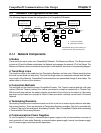
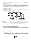
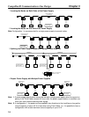
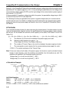
1 Locating the Nodes on Both Sides of the Power Supply
Power Supply Tap
or T-branch Tap
Communications
power supply
Node Node Node Node Node
2 Locating the Nodes on One Side of the Power Supply
Note Configuration 1 is recommended for a single power supply to several nodes.
Power Supply Tap
or T-branch Tap
Node Node Node Node Node
Communications
power supply
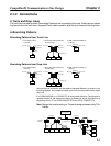
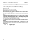
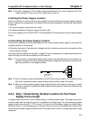
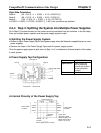
3 Splitting the Power Supply System with Multiple Power Supplies
Communications
power supply
Communications
power supply
System 1
Special Power Supply Tap
Remove the fuse
and split +V.
Make –V the same for
Systems 1 and 2.
Special Power Supply Tap
System 2
Node Node Node Node Node
V+
V–
fuse
24 V 0 V
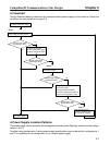
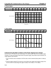
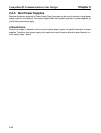
4 Duplex Power Supply with Multiple Power Supplies
Communications
power supply
Communications
power supply
Special Power
Supply Tap
Node Node Node Node
Node
Special Power
Supply Tap
Note 1. If power supply specifications cannot be met with a single power supply when the current ca-
pacity of the Thick Cable exceeds 8 A even after the power supply location is modified, use
more than one communications power supply.
Note 2. In configuration 1, the power can be supplied in two directions to the trunk line as long as the
current capacity of each is 8 A or less when using Thick Cable, i.e., it is possible to have a
configuration with a total maximum current capacity of up to 16 A.
CompoBus/D Communications Line Design Chapter 2