


3-2
3-1 Nomenclature and Settings
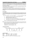
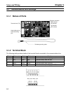
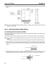
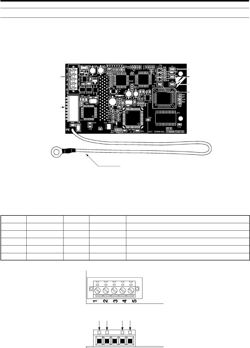
3-1-1 Names of Parts
Terminal block (TC)
Node address and
baud rate setting
pins
Operation indicators
PWR indicator
MS indicator
NS indicator
WD indicator
Shielded grounding cable
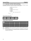
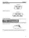
3-1-2 Terminal Block
The following table provides details of the terminal block connected to the communications line.
Display Sticker color Code Cable color Details
1 Black V– Black Communications power supply ground.
2 Blue CAN L Blue Communications data low side.
3 --- SG (Shield) Shield connection.
4 White CAN H White Communications data high side.
5 Red V+ Red Communications power supply, 24 VDC.
Black Blue White Red
Setup and Wiring Chapter 3