


3-7
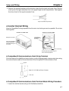
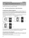
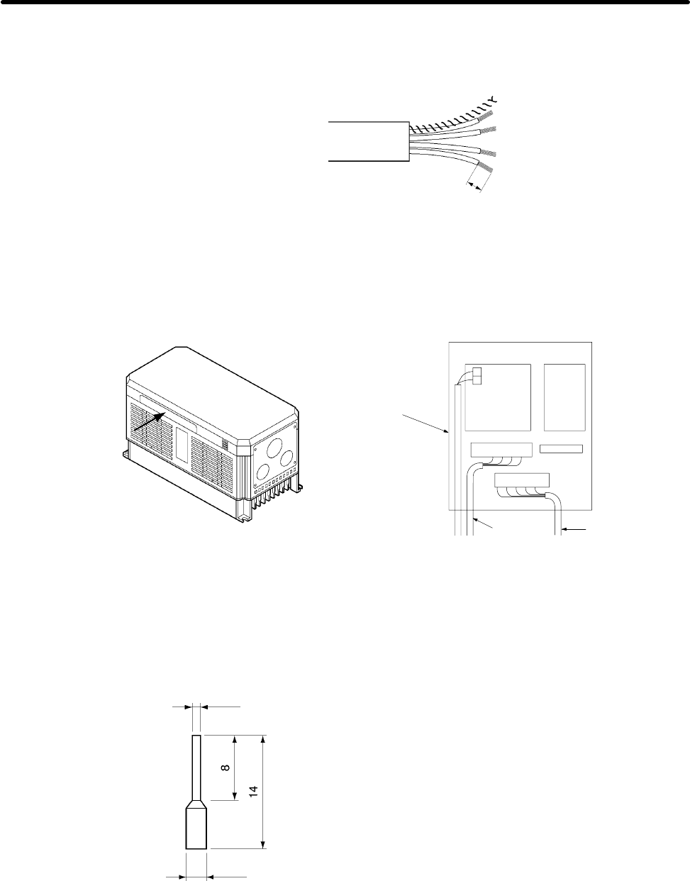
3. Remove the exposed weaving and the aluminum tape from the signal and power lines. Strip the
covering from the signal and power lines to the proper length for the crimp terminals. Twist together
the wires of each of the signal and power lines.
Strip to match the crimp terminals
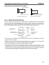
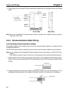
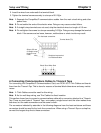
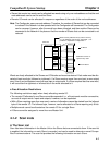
H Inverter Internal Wiring
Keep the CompoBus/D wiring separated from the main circuit wiring as much as possible. Do not wire
them together.
CompoBus/D
communications
line wiring
Control wiring
Main circuit wiring
Operator
CompoBus/D
Communications
Card
Side panel of Inverter
Pass the CompoBus/D
communications line
wiring by breaking off
this portion.
Inverters of 15 kW or Less Inverters of 18.5 kW or More
Do not bundle the control wiring and
main circuit wiring together.
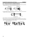
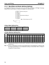
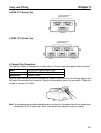
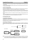
H CompoBus/D Communications Card Crimp Terminal
To further improve the reliability and ease of wiring, use the following straight crimp terminal when wiring
the communications cable to the terminal block of the CompoBus/D Communications Card.
Unit: mm
Model: A1 0.5–8 WH (by Phoenix Contact)
1.0 dia.
2.6 dia.
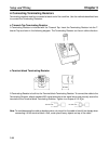
H CompoBus/D Communications Card Terminal Block Wiring Procedure
1. Loosen the terminal screws using a thin flat-blade screwdriver.
Setup and Wiring Chapter 3