


3-6
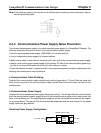
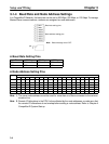
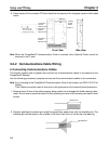
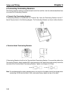
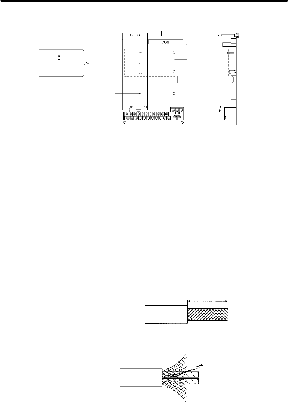
6. Press the top of the connector 2CN and check that the apexes of the triangular marks on both sides
match.
Connector
4CN for
option A area
Connector
2CN for
option C area
Connector
3CN for
option D area
Make sure that the
apexes of the black
triangular marks match
Option A
Option C
Control
Circuit
Board
Front View Side View
Note When the CompoBus/D Communications Card is mounted, other Optional Cards cannot be
mounted in the C area.
3-2-2 Communications Cable Wiring
H Connecting Communications Cables
This section explains how to prepare and connect the communications cables to connectors for the
CompoBus/D Network.
Use the following procedure to prepare and connect the communications cables to the connectors.
Note For connecting of the CompoBus/D Communications Card of the Inverter, use DCA1-5C10 Thin
Cables.
Thick Cables cannot be used for this kind of wiring because of the terminal block dimensions.
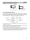
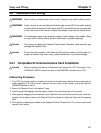
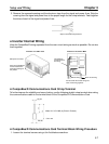
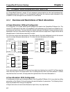
1. Remove about 30 mm of the cable covering, being careful not to damage the shield weaving under-
neath. Do not remove more than about 30 mm; removing too much of the covering can result in short
circuits.
About 30 mm
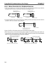
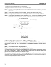
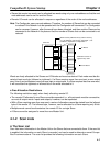
2. Carefully peel back the weaving to reveal the signal lines, power lines, and the shielding wire. The
shielding wire will be loose on the outside of the other lines, but it is harder than the weaving.
Shielding wire
Setup and Wiring Chapter 3