


MERLIN LEGENDCommunications System Release 6.1
System Planning
555-661-112
Issue 1
August 1998
Lines/Trunks
Page 3-32Selecting Line/Trunk Options
3
7. Under the Line Compensation heading:
a. Fill in the approximate distance (number of cable feet) between the
100D module and its CSU or other far-end connection in the space
before Cable Feet.
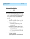
b. Use Table 3–4
to select the line compensation setting needed. (The
factory setting is 1.)
Table 3–4. Line Compensation Settings
*
Based on 22-gauge cable.
8. If the system includes both 800 NI-BRI and 100D modules, clock synchro-
nization planning should be completed at the same time. There is only one
primary/secondary/tertiary clock for both 800 NI-BRI modules and 100D
modules, with the same system programming screens used for both types.
If the switch is part of a private network, clock synchronization needs to be
coordinated for the entire network. See the
Network Reference
for
information.
Plan your clock source administration to minimize the need for clock
switching, which is known to cause noise on active calls.
Under Priority in the Clock Synchronization section, do
one
of the following:
■ If installing only one 100D module:
— To keep the factory setting, check Primary (that is, this
module provides synchronization for the system).
— If the synchronization source is other than through the 100D
module, check None.
■ If installing more than one 100D module, decide which module, if
any, provides the primary synchronization:
— If Module 1 provides clock synchronization, check Primary in
the first box (the factory setting).
— If Module 2 (or Module 3) provides clock synchronization,
check Primary in the box that describes that 100D module.
— If the synchronization source is other than through a 100D
module, check None.
Setting dB Loss Cable Feet*
1 (factory setting) -0.6 0−133
2 -1.2 133−266
3 -1.8 266−399
4 -2.4 399−533
5 -3.0 533−655