


MERLIN LEGENDCommunications System Release 6.1
System Planning
555-661-112
Issue 1
August 1998
Control Unit Configuration
Page 2-6Planning Module Placement
2
2. For each line/trunk and extension jack of each module, write the type of
jack (
X = extension; and L/T = line/trunk) and the associated logical ID,
keeping in mind the following:
■ Each 100D module is assigned 24 logical IDs, even though the
module has only 1 physical trunk jack.
■ Each 800 NI-BRI module is assigned 2 logical IDs per physical trunk
jack for a total of 16 logical IDs.
■ The 008 OPT module is assigned 12 logical IDs, even though the
module has only 8 physical extension jacks.
■ Power-failure transfer (PFT) jacks are not assigned logical IDs.
NOTES:
1. If the system will have one or more PFT telephones (maximum: 20),
indicate on the Control Unit Diagram the modules that will have PFT
telephones connected to their PFT jacks; write
PFT in the modules. A PFT
telephone can be connected to a PFT jack on a 400 LS, 400 GS/LS/TTR,
800, 800 GS/LS, 800 GS/LS-ID, 408, 408 GS/LS, or 408 GS/LS-MLX
module. Touch-tone PFT telephones must be connected to jacks with
touch-tone lines/trunks.
2. You need a ground-start button on a PFT telephone connected to a
ground-start trunk.
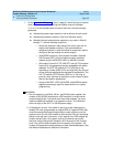
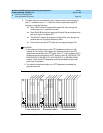
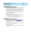
Figure 2–1. Sample Control Unit Diagram
Power
Supply
Power
Supply
BASIC CARRIER
EXPANSION CARRIER
EXPANSION CARRIER
00 01 02 03 04 05 06 07 08 09 10 11 12 13 14 15 16 17
Power
Supply
Ring Generator
Ring Generator
Ring Generator
X8
X7
X6
X5
X4
X3
X2
X1
X16
X15
X14
X13
X12
X11
X10
X9
X24
X23
X22
X21
X20
X19
X18
X17
X32
X31
X30
X29
X28
X27
X26
X25
X40
X39
X38
X37
X36
X35
X34
X33
X52
X51
X50
X49
X48
X47
X46
X45
X44
X43
X42
X41
L/T4
L/T3
L/T2
L/T1
L/T8
L/T7
L/T6
L/T5
L/T12
L/T11
L/T10
L/T9
L/T16
L/T15
L/T14
L/T13
L/T24
L/T23
L/T22
L/T21
L/T20
L/T19
L/T18
L/T17
L/T32
L/T31
L/T30
L/T29
L/T28
L/T27
L/T26
L/T25
OO8 MLX
408
408
OO8 MLX
400 GS/LS/TTR
012
408 GS/LS
800
800