


MERLIN LEGENDCommunications System Release 6.1
System Planning
555-661-112
Issue 1
August 1998
Before You Begin
Page 1-2Confirming the Location of the Control Unit
1
Confirming the Location of
the Control Unit 1
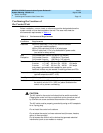
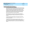
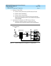
Before installation, a room, closet, or other area must be designated where the
system control unit can be mounted on the wall. The area must meet the
environmental requirements in Table 1–1
.
Table 1–1. Environmental Requirements
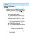
!
CAUTION:
The AC outlet for the control unit should not be switch-controlled.
Plugging the control unit into an outlet that can be turned on and off
by a switch can cause accidental disconnection of the system.
The AC outlet must be properly grounded by using an AC receptacle
for a 3-prong plug.
Do not install the control unit outdoors.
Do not place the control unit near extreme heat (furnaces, heaters,
attics, or direct sunlight).
Do not expose the control unit to devices that generate electrical
interference (such as arc welders or motors).
Conditions Requirements
Distances Within 25 cable feet (7.6 m) of the network interface
(cannot be installed outdoors)
Within 1000 cable feet (304.8 m) of telephones
Within 5 cable feet (1.5 m) of a dedicated AC power outlet
(one outlet for every carrier)
Heat
Dissipation
Fully loaded basic carrier: 500 Btu/hr (35 cal/sec)
Fully loaded 2-carrier: 1000 Btu/hr (70 cal/sec)
Fully loaded 3-carrier: 1500 Btu/hr (105 cal/sec)
Power Basic carrier: 117 VAC 60 Hz ± 5% 160 W 5.4 amps
2-carrier: 117 VAC 60 Hz ± 5% 320 W 10.8 amps
3-carrier: 117 VAC 60 Hz ± 5% 480 W 16.2 amps
one properly grounded outlet needed for each carrier
Additional outlets may be needed if installing printers and PCs.
Temperature 40° through 104°F; 4° through 40°C
(optimal temperature 60°F; 16°C)
Humidity 20% through 80% relative humidity
Ventilation Allow at least 1 in. (2.5 cm) of space on the right and left sides of
the control unit and 12 in. (30.5 cm) above and below the
control unit to prevent overheating.