


MERLIN LEGENDCommunications System Release 6.1
System Planning
555-661-112
Issue 1
August 1998
Control Unit Configuration
Page 2-2Planning Module Placement
2
Planning Module Placement 2
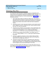
In addition to the processor module and power supply module, the system
supports several types of line/trunk and extension modules. Deciding how to
place the modules in the carriers consists of the following tasks:
1. Calculating the system’s line/trunk capacity according to module types
2. Calculating the system’s extension capacity according to module types
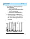
3. Mapping out module placement on the Control Unit Diagram, according to
specific guidelines
This section contains instructions for each of these tasks.
For information about calculating unit load requirements, see Appendix F, “Unit
Load Calculation”.
For detailed information about modules and their specifications (including
line/trunk and extension capacity), see the descriptions of hardware components
contained in the
Pocket Reference.
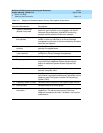
Forms Needed 2
■ Equipment List (if available)
■ Form 1, System Planning
Capacity for Lines/Trunks 2
Line/trunk capacity is the number of lines/trunks that can be connected to the
control unit. This section contains instructions for calculating the systems capacity
for lines/trunks, according to the system’s module types.
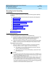
Planning Form Instructions 2
1. In the table in the Line/Trunk Capacity section of Form 1, System Planning,
fill in the number of each type of line/trunk module on the appropriate line of
the Number of Modules column.
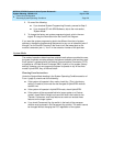
2. Add the column and record the result at the bottom of the column on the
System Totals line.
3. For each module type noted, multiply the value in the Number of Modules
column by the value in the Trunks Supported by Module column; write the
results in the appropriate row under Total Trunks by Module Type.
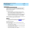
4. Add the column and record the total line/trunk capacity of the system at the
bottom of the column, on the System Totals line.