


MERLIN LEGENDCommunications System Release 6.1
System Planning
555-661-112
Issue 1
August 1998
Control Unit Configuration
Page 2-22Numbering the System
2
7. To indicate the primary DLC operator position:
■ Locate the first extension jack showing a jack type of D (digital) or A
(analog) and write
DLC beside the preprinted logical ID number.
■ Write the name or location of the primary DLC operator in the
Person, Location, or Function column.
■ On Form 1 (page 2), write the extension of the DLC under System
Consoles.
Proceed to the next section, “Jacks for Additional Operator Positions”.
Jacks for Additional Operator Positions 2
Use these instructions only if the system has more than one operator position.
Otherwise, skip to the next section, “Extension Jack Pairs for Analog Telephones”.
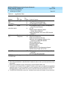
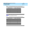
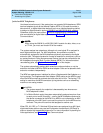
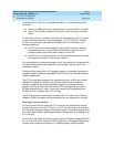
The maximum number of operator positions is shown in Table 2–7
.
Table 2–7. Maximum Number of Operator Positions
Any combination of operator positions can be assigned as long as no more than
four are QCCs and the total combined number is no more than eight. For
example, a system can have a combination that consists of four QCCs, two MLX
DLCs, and two analog DLCs. The Call Management System (CMS) equipment
connects to analog extension jacks assigned as DLC positions. You must assign
two DLC positions for each CMS (maximum of two) connected to the system on
analog multiline modules.
Planning Form Instructions 2
NOTE:NOTE:NOTE:
For each CMS connected to the system, you must assign two analog DLC
positions. These two DLCs do
not
need to have the factory setting
extension numbers but do need to be on the same module.
Position Telephone Maximum
QCC MLX-20L 4
DLC MLX-20L
MLX-28D
8
DLC Analog multiline
telephones
8