


MERLIN LEGENDCommunications System Release 6.1
System Planning
555-661-112
Issue 1
August 1998
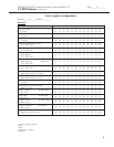
Unit Load Calculation
Page F-5Unit Load Worksheet
F
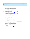
* Unit loads are computed for each trunk for trunk-type network access lines.
† The MFM has its own wall power unit located at the telephone and therefore is not added to the
unit load calculation.
‡ Up to two DSSs (one DSS for each MLX-28D or MLX-20L) can be powered from each control
unit carrier. For example, a three-carrier system can have six system operator positions, each
with one DSS powered from the control unit.
Module Qty x Unit Load = Total
Equipment
Hybrid/PBX
or Modified
Key
Network Access Lines*
DID 1.0 0.0
DS1 0.0 0.0
NI-1 BRI 0.0 0.0
GS/LS 0.0 0.0
Tie 1.4 1.4
Telephones
MLX-5 0.9 1.2
MLX-5D 0.9 1.2
MLX-10 0.9 1.2
MLX-10D 0.9 1.2
MLX-10DP 0.9 1.2
MLX-16DP 1.5 1.5
MLX-28D 1.2 1.7
MLX-20L 1.1 1.6
BIS-10 0.9 1.1
BIS-22 1.0 1.3
BIS-22D 1.0 1.3
BIS-34 1.1 1.5
BIS-34D 1.1 1.5
MLC-5 0.0 0.0
MDC 9000 0.0 0.0
MDW 9000 0.0 0.0
10-Button Basic 0.9 1.1
10-Button HFAI 1.0 1.2
34-Button Basic 0.9 1.1
34-Button DLX 1.2 1.7
34-Button BIS 1.2 1.4
34-Button BIS/DIS 1.2 1.4
Single-Line Telephone 0.6 0.7
Optional Equipment
†
Direct Station Selector
‡
0.7 0.9
General-Purpose Adapter 0.8 1.0
Hands-Free Unit 0.8 1.0
Headset Adapter 0.8 1.0
EICON board 0.0 0.0
Total Actual Unit Load