


MERLIN LEGENDCommunications System Release 6.1
System Planning
555-661-112
Issue 1
August 1998
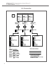
T1/PRI Planner
Page D-3
D
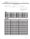
9. To ensure that the synchronization integrity of the DS1 network both
this communications system and its far-end connections
is protected,
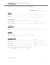
prepare the DS1 Planning Map on page 4 for review by SDSC. Describe
the entire network of DS1 facilities by summarizing the following for each
100D module:
a. Fill in the control unit slot number(s) of the 100D modules connected
to the CSU(s).
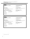
b. Write the approximate number of cable feet between each module
and its CSU or far-end connection (refer to the Line Compensation
entry on Form 3b, Page 1).
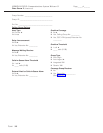
c. For the model number(s) of the CSU(s), do
one
of the following:
■ If the CSU is the ACCULINK 3150, check the box for the
ACCULINK 3150.
■ If the CSU is not the ACCULINK 3150, check the Other box
and write the manufacturer’s name and model number in the
space provided at the bottom of the page.
■ If no CSU is needed, check None.
d. In the connection block(s), describe the DS1’s far-end connection by
doing
one
of the following:
■ If connected to the telephone company central office, check
CO.
■ If connected to another communications system, check PBX.
■ If connected to the PRI network, check PRI.
■ If the facility’s type of service is T1, check the type(s) of
emulated trunks. Also, check the Services box if the facility
includes services such as MultiQuest with DNIS.
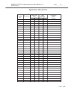
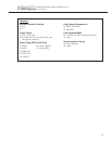
e. Describe the clock synchronization sources according to the key at
the lower left of the map.
i. Draw a circle and line from the clock source to the
appropriate 100D module.
ii. Label the circle
P for primary, S for secondary, or T for tertiary.
10. Make a copy of the T1/PRI Planner for your records and forward the
original to SDSC.
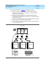
As an example, the system described in Figure D–1
shows a processor module
system with two 100D modules.