


MERLIN LEGENDCommunications System Release 6.1
System Planning
555-661-112
Issue 1
August 1998
Control Unit Configuration
Page 2-23Numbering the System
2
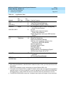
1. On the Control Unit Diagram on Form 1, determine which extension jacks
can be used as operator positions by circling the first and fifth extension
jacks on digital or analog modules, until you have reached the maximum
number of eight positions.
2. On Form 2a, mark the extension jacks to be used as additional operator
positions.
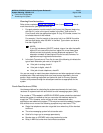
3. Do
one
of the following:
■ If the system has additional QCCs, proceed to Step 4.
■ If the system has additional DLCs, skip to Step 5.
4. For each additional QCC:
■ Write QCC next to the preprinted logical ID for each additional QCC
position. Be sure to assign QCCs to only the first and fifth extension
jacks on each digital module.
■ Write the name or location of each additional QCC operator in the
Person, Location, or Function column.
■ On Form 1 (page 2), write the extension number of each additional
QCC in the System Consoles box.
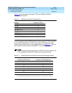
5. For each additional DLC:
■ Write DLC next to the preprinted logical ID for each additional DLC
position, including DLC positions used for calling group supervisors
and for the optional CMSs. Be sure to assign DLCs to only the first
and fifth extension jacks on each digital or analog module.
■ Write the name or location of each additional DLC operator in the
Person, Location, or Function column.
■ On Form 1 (page 2), write the extension number of each additional
DLC in the System Consoles box.
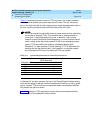
6. If the system includes any Call Management Systems, write
CMS in the
Person, Location, or Function column next to the logical ID for the two DLC
positions assigned for each CMS.
Proceed to the next section, “Extension Jack Pairs for Analog Telephones”.