


MERLIN LEGENDCommunications System Release 6.1
System Planning
555-661-112
Issue 1
August 1998
Control Unit Configuration
Page 2-25Numbering the System
2
Jacks for MLX Telephones 2
Use these instructions only if the system has non-operator MLX telephones, ISDN
terminal adapters (such as the Ascend Pipeline 25PX or 50) used to connect a
data terminal, or digital data/video stations (such as a videoconferencing station)
to assign to digital extension jacks on 008 MLX and 408 GS/LS-MLX modules.
Otherwise, skip to the next section, “Jacks for Analog Multiline Telephones”. To
plan connections for digital data equipment, see Chapter 5, “Data
Communications”.
NOTE:NOTE:NOTE:
When using the 008 MLX or 408 GS/LS-MLX module for data, video, or as
a CTI link, you must use Version 28 of the module.
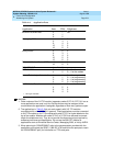
The system assigns two extensions, although only one logical ID is assigned to
each digital extension jack. For MLX telephones, one extension number is
automatically assigned to the MLX telephone physically connected to the digital
extension jack. The second extension number is reserved for an adjunct, such as
an analog modem or Delay Announcement Device, that can be connected to the
MLX telephone through a Multi-Function Module (MFM). For information about
renumbering jacks, see “System Renumbering” later in this chapter.
The system automatically assigns both extension numbers whether or not the
extension includes an MFM or ISDN terminal adapter. Calls can be placed to both
extension numbers independently.
The MFM can operate as an interface for either a Supplemental Alert Adapter or a
tip/ring device. The Supplemental Alert Adapter (SAA) setting on the MFM is used
when the MFM connects an external alert such as a bell or horn. The tip/ring (T/R)
setting is used when the MFM connects a tip/ring device such as an answering
machine or an analog modem.
NOTES:
1. The system capacity for endpoints is decreased by two whenever an
MLX telephone is used.
2. In Behind Switch mode, the system automatically assigns two prime lines
to each port on an MLX module — one for the MLX telephone and one for
the device connected to the MFM. If an MFM is not connected to an MLX
telephone or the MLX port is not used, the prime line for the MFM can be
removed. The prime line can then be assigned to another user.
When PRI, NI-1 BRI, or T1 Switched 56 lines/trunks are assigned to an MLX jack,
digital data/video stations may use two B-channels simultaneously (2B Data) to
place or receive high-speed data/video calls. For more information on planning for
video applications, see Chapter 5, “Data Communications”.