


MERLIN LEGENDCommunications System Release 6.1
System Planning
555-661-112
Issue 1
August 1998
Control Unit Configuration
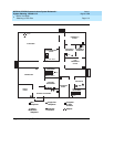
Page 2-3Planning Module Placement
2
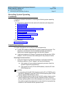
Capacity for Extensions 2
Extension capacity is the number of extensions that can be connected to the
control unit. In most cases, the number of physical jacks on the modules indicates
capacity. Most loop-start and ground-start modules have one or two power-failure
transfer (PFT) jacks used to connect a single-line telephone in case of a power
failure, and not counted in system capacity. Every four line jacks has one
associated PFT jack.
One extension number is automatically assigned to each extension jack, whether
or not equipment is connected to it, except for the 008 MLX, 408 GS/LS-MLX, and
008 OPT modules:
■ 008 MLX and 408 GS/LS-MLX Modules. Two extension numbers are
assigned to each physical jack: the first for an MLX telephone and the
second for any equipment connected to the telephone through an MFM,
ISDN terminal adapter (such as the Ascend Pipeline 25 or 50), or any 2B
data desktop video endpoint.
NOTE:
When using the 008 MLX or 408 GS/LS-MLX module for data or
video, you must use Version 28 of the module.
■ 008 OPT Module. The system recognizes this module as an 012 module.
Therefore, even though the OPT module has only 8 physical jacks, it uses
12 ports of capacity. An extension number is assigned to each of the 8
physical jacks.
This section contains instructions for calculating the system’s extension capacity,
according to the number of certain module types.
Planning Form Instructions 2
1. In the table under the Extension Capacity section of Form 1, fill in the
number of each type of extension module on the appropriate line of the
Number of Modules column.
■ Each 100D module is assigned 24 logical IDs, even though the
module has only 1 physical trunk jack.
■ Each 800 NI-BRI module is assigned 2 logical IDs per physical trunk
jack for a total of 16 logical IDs.
2. Add the column and record the result at the bottom of the column
(System Totals line).
3. For each module, multiply the value in the Number of Modules column by
the value in the Physical Jacks per Module column and record the results
on the appropriate line in the Physical Jacks by Module Type column.
4. Add the column and record the results at the bottom of the column
(System Totals).