


MERLIN LEGENDCommunications System Release 6.1
System Planning
555-661-112
Issue 1
August 1998
Control Unit Configuration
Page 2-5Planning Module Placement
2
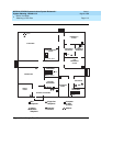
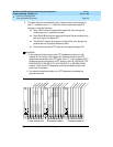
1. On the Control Unit Diagram of Form 1 (page 2), record the type of module
to be installed in each slot by writing the module name (for example,
008 MLX) on the slanted lines at the top of each slot. Use the following
guidelines:
■ Indicate the power supply module in the far left slot of each carrier.
■ Indicate the processor module in Slot 00 of the basic carrier.
■ Indicate line/trunk and extension modules in any order in Slots 01
through 17, with the following conditions:
— Group the modules in each carrier from left to right with no
empty slots between modules. (The system does not
recognize modules in slots that follow an empty slot; slots to
the right of the last module can be left empty.)
— (Hybrid/PBX mode only) If the system includes a Queued
Call Console (QCC), the first line/trunk and/or extension
module must be a 408 GS/LS-MLX or 008 MLX module.
— (All modes) Current 012 T/R, 008 OPT, and 016 T/R modules
have built-in ring generators and are compatible with earlier
releases. The 012 T/R module [517J13 (28)] has a ring
equivalency number (REN) of 2.2 and rings only four ports at
a time, although eight jacks can be used for applications. The
016 T/R module (517C34) has a REN of ≥ 4, can ring 16
ports at a time, and has no restriction on the number of jacks
that can be used for applications.
— Group all 800 DID, 100D, 800 NI-BRI, and 400EM modules
together according to type; this helps save time in system
programming.
NOTES:
1. Due to limitations in the 391A, 391A1, and 391A2 power supplies, the
number of 800 NI-BRI modules plus 100D modules in a single carrier
cannot exceed three. If you have more than three modules, you must
install the additional modules in an expansion carrier. This restriction
does not apply to the 391C1 or 391A3 power supply.
2. In Release 6.0 or later, if the switch is part of a private network and a
tandem PRI trunk (programmed as Legend-PBX or Legend-NTWK) has
some B-channels that would bring the total number of trunks over the
system limit of 80, the 100D module for that tandem PRI trunk should be
placed in the last slot in the carrier. In this manner, the 100D module will
contain the last lines in the system, and any B-channel over the 80
line/trunk limit will be ignored. However, the D-channel will still function
even if the 100D module exceeds the line capacity of the system. The
number of B-channels must be the same on each networked system. See
the
Network Reference
for additional information.