


MERLIN LEGENDCommunications System Release 6.1
System Planning
555-661-112
Issue 1
August 1998
Control Unit Configuration
Page 2-4Planning Module Placement
2
5. To determine the number of extensions assigned for each module type,
multiply the value in the Physical Jacks by Module Type column by the
value in the Extensions Assigned column and write the results in the
appropriate row in the Total Extensions Assigned column.
NOTE:
Since the system assigns an additional four extensions to each
008 OPT module, you must first calculate the Extensions Assigned
by multiplying the number of 008 OPT modules (noted in the Number
of Modules column) by 4 and then add this subtotal to the number
noted in the Physical Jacks by Module Type column.
6. Add the column and record the result at the bottom of the column
(System Totals).
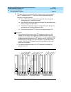
Control Unit Diagram—Module Placement 2
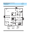
This section describes how to use the Control Unit Diagram on Form 1 (page 2) to
map the placement of the modules according to certain guidelines. Figure 2–1 on
page -6 provides an example of a Control Unit Diagram for a system with 32
lines/trunks and 52 extensions. In addition, this section describes how to identify
each jack on each module with respect to type (line/trunk or extension) and its
associated logical ID. Each physical jack on the control unit is numbered
sequentially from bottom to top and left to right with logical IDs as follows:
■ Extension jacks are numbered from 1 to 200.
■ Line/trunk jacks are numbered from 1 to 80.
This sequence of logical IDs is the basis for connecting components to the control
unit, as well as for the assignment of extension numbers and line/trunk numbers.
Planning Form Instructions 2
NOTE:NOTE:NOTE:
The Unit Load blocks above the diagram are reserved for equipment
changes or maintenance. A Lucent Technologies representative or
authorized dealer computes these values manually.