


Appendix A - Advanced Display Module (ADM)
104 3A2098H
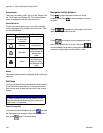
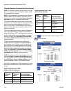
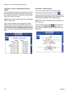
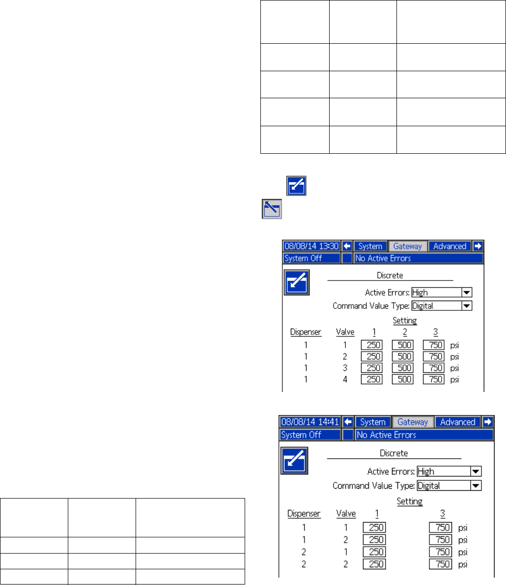
Discrete Gateway (Automation) Setup Screen
NOTE: The Discrete Gateway Setup screen is not avail-
able if an automation Discrete Gateway Module (DGM)
is not attached to the system.
NOTE: If Swirl Dispensers are installed, a Swirl Discrete
Gateway Module will be installed. This section is not
related to that module. See Control Center Assembly
Overview on page 16 for gateway identification.
This screen enables users to set Active Errors to High
(default) or Low. If High is selected, alarm and error sig-
nals are low during normal operation and high if an
alarm or error exists. If Low is selected, alarm and error
signals are high under normal operation and low if an
alarm or error exists.
This screen also enables users to select the Command
Value Type signal (Analog or Digital) the automation
system will provide to PCF. If Analog control is selected,
the user must provide an analog voltage to the proper
input on the DGM. See Appendix B - Discrete Gate-
way Module (DGM) Connection Details, page 115, for
connection details.
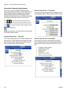
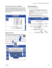
If Digital control is selected and one fluid plate is
installed, the user can define three digital settings for
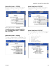
each dispense valve. If Digital control is selected and
two fluid plates are installed, the user can define two
digital settings for each dispense valve. The user must
provide two digital signals to the proper inputs on the
DGM. See Appendix B - Discrete Gateway Module
(DGM) Connection Details, page 115, and the Digital
Command Logic Table for connection details.
NOTE: The control mode for each dispense valve is set
in the Fluid Plate x, Screen 2 (Mode Settings), page
105. For example, if Valve 1 is set to Pressure mode on
the Fluid Plate x, Screen 2 (Mode Settings), then the
digital commands for Valve 1 are pressure values.
The Digital Command Logic Table indicates which value
each input must be set to in order to select a particular
setting.
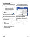
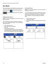
Digital Command Logic Table
(Single Fluid Plate Systems)
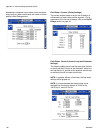
Digital Command Logic Table
(2-Fluid Plate Systems)
Press to access the fields to make changes. Press
to exit edit mode.
Digital
Command
Input 1
Digital
Command
Input 2
Resulting Digital
Command Selection
Low
Low Setting #1
High
Low Setting #2
---
High Setting #3
Digital
Command
Input 1
Digital
Command
Input 2
Resulting Digital
Command Selection
Low
--- Fluid Plate 1,
Setting #1
High
--- Fluid Plate 1,
Setting #2
--- Low
Fluid Plate 2,
Setting #1
--- High
Fluid Plate 2,
Setting #2
Single fluid plate system
2-fluid plate system