


Installation
28 3A2098H
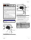
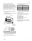
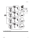
Install Cable Assemblies
NOTE: To prevent system errors, only connect cables
with the power off.
NOTE: See F
IG
. 17 on page 29.
1. For systems with more than one swirl dispenser:
Use a CAN cable to connect the control center to
one swirl expansion enclosure. Use additional CAN
cables to connect any remaining expansion swirl
enclosures together in sequence.
2. For systems with one or more swirl dispensers,
use
motor cable to connect each swirl dispenser to an
expansion swirl enclosure or to the control center.
3.
Connect a CAN cable from the control center to one
fluid plate assembly.
4.
For multiple fluid plate systems,
use CAN cables to
connect each fluid plate to one other fluid plate
Repeat until all fluid plates are connected to one
other fluid plate.
NOTE: Use the connections on the CAN splitter on the
left side of each fluid plate to connect the fluid plates
together. There will be a CAN splitter on all but one fluid
plate.
NOTE: The control center, expansion swirl enclosures,
and fluid plates may be connected in any order as long
as each is connected to another system component with
a CAN cable. See the example shown in F
IG
. 17 on
page 29.
5. Use the automation interface cable (not provided) to
connect the Gateway module to the automation
controller.