Appendix B - Discrete Gateway Module (DGM) Connection Details
3A2098H 115
Appendix B - Discrete Gateway Module (DGM) Connection Details
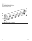
D-Sub Cable 123793
The D-sub cable 123793 is only compatible with single fluid plate systems. Systems with 2 fluid plates must use
cable 123792 and breakout board 123783.
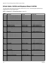
The cable length of interface cable assembly 123793 is 50 ft (15.2 m). The following table identifies the cable inter-
face signals.
NOTE: See Appendix D - I/O Signal Descriptions, page 138, for I/O signal descriptions.
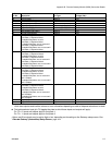
◆
Swirl-related inputs apply only to systems with Swirl Dispensers.
* Dispense Error may be active high or low, depending on the setting on the Gateway setup screen. See Discrete
Gateway (Automation) Setup Screen, page 104.
Wire Color Description Pin Type
D-Sub
Pin No.
Green/Yellow Isolated Logic Power Supply Supply 51 and 27
Gray Isolated Logic GND Supply 70
Blue/Green Dispense Ready Digital Output 9
Brown/Green Dispense Error* Digital Output 11
Blue/Orange Dispense In Process Digital Output 12
White Dispense Purge Digital Output 15
Blue Dispense Remote Start Digital Output 16
White/Yellow Style Bit 1 Digital Input 52
Blue/Yellow Style Bit 2 Digital Input 53
Brown/Yellow Style Bit 3 Digital Input 54
Black/Red Style Bit 4 Digital Input 55
White/Red Style Strobe Digital Input 56
Blue/Red Dispense Complete Digital Input 57
Brown/Red Error Reset Digital Input 58
Black Remote Start/Purge Digital Input 59
Black/Gray Dispense Valve 1 Digital Input 73
Brown/Orange Dispense Valve 2 Digital Input 74
Brown Command Value Analog Input 1
Black/Yellow Analog GND Analog Input 2
White/Gray --- 3
Blue/Gray Swirl 1 Speed Command ◆ Analog Input 21
Brown/Gray Swirl 2 Speed Command ◆ Analog Input 23
White/Orange
Dispense Valve 3/
Swirl 1 Enable◆
Digital Input 75
Black/Orange
Dispense Valve 4/
Swirl 2 Enable◆
Digital Input 76
Black/Green Digital CMD 1 Digital Input 77
White/Green Digital CMD 2 Digital Input 78
Orange --- N/C


