


Appendix D - I/O Signal Descriptions
138 3A2098H
Appendix D - I/O Signal Descriptions
This section provides details about the CGM and DGM
Automation Input and Output signals.
Automation Inputs
Dispenser (Fluid Plate) Ready
This signal is 0 on power up. This signal will be 1 under
in the following conditions:
• The system is in an active state, and
• The dispenser (fluid plate) does not have an
active Alarm (Deviations have no effect).
Dispenser (Fluid Plate) No Alarm
For systems with a CGM, this signal will be 1 under the
following condition:
• The system does not have an alarm.
• For systems with a DGM, this signal can be
configured to be active high or active low.
See
Discrete Gateway (Automation) Setup
Screen, page 104.
Dispenser (Fluid Plate) No Error
For systems with a CGM, this signal will be 1 under the
following condition:
• The system does not have an error (alarm, devi-
ation, or advisory).
• For systems with a DGM, this signal can be
configured to be active high or active low.
See
Discrete Gateway (Automation) Setup
Screen, page 104.
Dispense in Process
This signal is 0 on power up. This signal will be 1 under
the following condition:
• The system is in the middle of a job.
Dispense Volume OK
This signal will be 1 under the following conditions:
• The system has completed a job, and
• the volume of the job is within the tolerance
specified, and
• the style strobe is 1.
Dispenser (Fluid Plate) Purge Request
This signal is 1 on power up if a purge interval has been
defined, 0 on power up otherwise. Any dispensing will
turn off this bit and reset the purge timer. This signal will
be 1 under the following condition:
• The system purge interval timer has expired.
Dispenser (Fluid Plate) Remote Start / Purge in
Process
This signal is 0 on power up. This signal will be 1 under
the following conditions:
• A remote start sequence is in process. This sig-
nal shall remain asserted until the dispense
equipment has achieved Dispense Ready sta-
tus.
• A purge sequence is in process. This signal
shall remain asserted until the purge sequence
is complete.
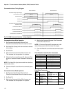
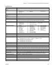
Units
All units settings are set in the Advanced Display Mod-
ule. The following signals are used to communicate this
information to the automation controller.
Pressure Units
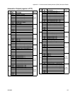
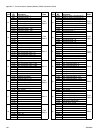
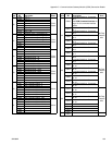
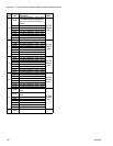
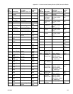
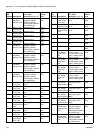
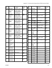
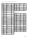
Errors
Error numbers are formed by 8 bits. This is the error
number in the system.
Value Units
0
psi
1
bar
2
MPa
3
reserve