System Setup
32 3A2098H
System Setup
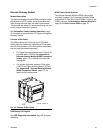
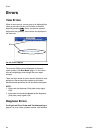
Overview
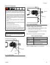
The PCF system compensates for temperature, flow, or
pressure fluctuations. However, if there is a hardware
change on the supply system or the dispense material is
changed, the PCF system must be set up again.
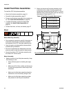
After material is loaded into the supply system, set up
the PCF system using the Setup screens. The following
procedure outlines the major system setup steps. The
following subsections provide instructions to complete
each setup step. Once these steps are complete the
module is ready for operation.
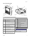
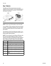
NOTE: See the Advanced Display Module (ADM) sec-
tion, page 17, and Appendix A - Advanced Display
Module (ADM), page 99, for detailed operating instruc-
tions for the display keypad and each screen.
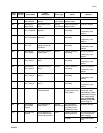
1. Configure System, page 32.
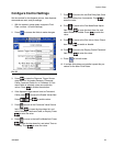
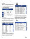
2. Configure Control Settings, page 33.
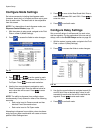
3. Configure Mode Settings, page 34.
4. Configure Delay Settings, page 34.
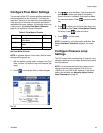
5. Configure Flow Meter Settings, page 35.
6. Configure Pressure Loop Settings, page 35.
7. Adjust Pressure Sensors, page 36.
8. Configure Errors, page 36.
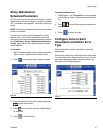
9. Setup Maintenance Schedule/Parameters, page 37.
10. For systems with swirl dispensers only:
a. Configure Swirl to valve association and error
type, page 37.
b. Configure Swirl settings, page 38.
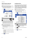
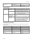
11. Configure Gateway Settings, page 38.
12. Setup Styles, page 38.
13. Configure Advanced Settings, page 38.
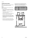
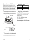
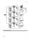
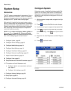
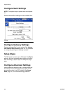
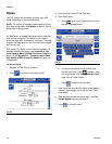
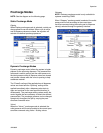
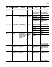
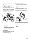
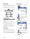
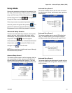
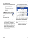
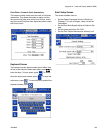
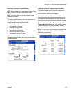
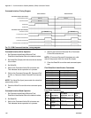
Configure System
Define the number of installed fluid plates (called “Dis-
penser” on this screen) and number of installed swirl
dispensers. If a fluid plate is listed as “Uninstalled” the
screens for that fluid plate will not appear in the run or
setup screens.
1. With the system in setup mode, navigate to the Sys-
tem screen.
2. Press to access the fields to make changes.
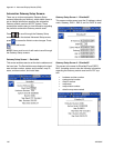
3. Use the arrow keys to navigate to the desired field.
4. Press to open the drop-down list, and select
the desired setting. Press to accept the selec-
tion.
5. Repeat for the other Dispensers and Swirl Dispens-
ers.
6. Press to exit edit mode.
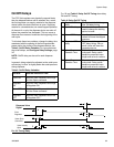
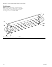
F
IG
. 19