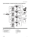
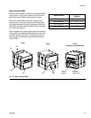
Installation
3A2098H 21
Installation
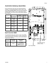
Before Installation
• Have all system and component documentation
available during installation.
• See component manuals for specific data on compo-
nent requirements. Data presented here applies to
the PCF assemblies only.
• Be sure all accessories are adequately sized and
pressure-rated to meet system requirements.
• Use the PCF control center only with the PCF fluid
plate assembly.
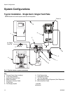
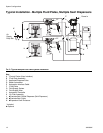
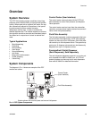
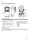
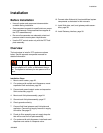
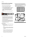
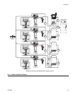
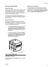
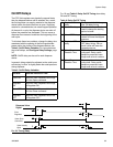
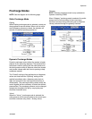
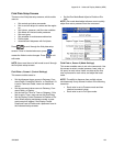
Overview
The basic steps to install a PCF system are shown
below. See the separate component manuals for
detailed information.
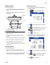
Installation Steps
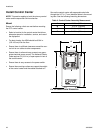
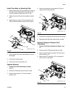
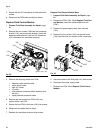
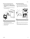
1. Mount control center, page 22.
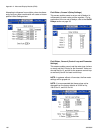
2.
For systems with multiple swirl dispensers,
mount
expansion Swirl enclosures, page 22.
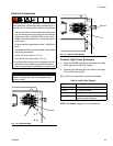
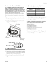
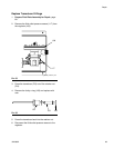
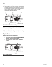
3. Connect and ground control center and expansion
Swirl enclosures, page 23.
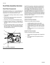
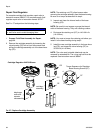
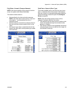
4. Mount each fluid plate assembly, page 24.
5. Ground each fluid plate assembly, page 27.
6. Check ground continuity.
7. Connect fluid lines between each fluid plate and
applicator. Connect fluid supply line and air supply
to module. See page 27.
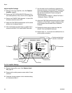
8. Plumb air filter assembly near air supply drop site
that will be used for fluid plate assembly.
9. For systems with swirl dispensers,
install each swirl
dispenser onto outlet of a dispense valve.
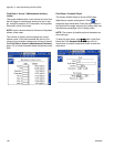
10. Connect other fluid and air lines to additional system
components as instructed in their manuals.
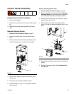
11. Install fluid plate, swirl, and gateway cable assem-
blies, page 28.
12. Install Gateway interface, page 30.
To avoid injury and damage to equipment, use at
least two people to lift, move, or disconnect the sys-
tem. The system is too heavy for one person to lift or
move.