


Technical Data
140 3A2098H
Technical Data
* Flow rates and viscosities are general estimates. Flow rates drop as viscosity increases. Fluids are expected to
shear under pressure. New applications or fluids should always be tested to determine proper line sizes and equip-
ment selections. See your Graco authorized distributor for other capabilities.
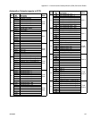
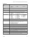
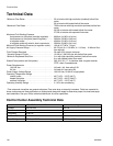
Control Center Assembly Technical Data
*Minimum Flow Rates . . . . . . . . . . . . . . . . . . . . . . . . . . . 25 cc/minute with high-resolution (ambient) helical flow
meter
50 cc/minute with heated helical flow meter
*Maximum Flow Rates . . . . . . . . . . . . . . . . . . . . . . . . . . . 7500 cc/minute with high-resolution (ambient) helical flow
meter
22,500 cc/minute with heated helical flow meter
37,500 cc/minute with separate flow meter
Maximum Fluid Working Pressure
feed pressure to fluid plate (cartridge regulator) . . . .
feed pressure to fluid plate (mastic regulator) . . . . . .
at regulator outlet. . . . . . . . . . . . . . . . . . . . . . . . . . . .
at regulator outlet with electric heat components . . .
6000 psi (41 MPa, 414 bar)
5000 psi (35 MPa, 345 bar)
4500 psi (31 MPa, 310 bar)
3500 psi (24 MPa, 241 bar)
Minimum Fluid Working Pressure (at regulator outlet). . . 100 psi (0.7 MPa, 7.0 bar)
Air Supply Pressure Range . . . . . . . . . . . . . . . . . . . . . . . 60-120 psi (0.4 - 0.8 MPa, 4.1- 8.3 bar) - 10 Micron filtra-
tion required
Fluid Filtration Required. . . . . . . . . . . . . . . . . . . . . . . . . . 30 mesh (500 micron) minimum
*Viscosity Range of Fluids . . . . . . . . . . . . . . . . . . . . . . . . 10,000 to 1,000,000 cps with helical flow meter
*Minimum Dispensed Shot Size. . . . . . . . . . . . . . . . . . . . 3 cc with high-resolution (ambient) helical flow meter
6 cc with heated helical flow meter
Wetted Parts (meters and fluid plates). . . . . . . . . . . . . . . 303, 304, 321, 17- 4 stainless steel; tungsten carbide,
PTFE, steel, fluoroelastomer
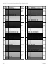
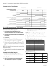
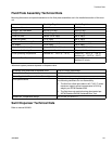
Power Requirements
100-240 Vac . . . . . . . . . . . . . . . . . . . . . . . . . . . . . . .
24 Vdc . . . . . . . . . . . . . . . . . . . . . . . . . . . . . . . . . . . .
full load-1.4A, fuse rating-2.5A
full load-4A, fuse rating-4A
Power Supply Voltage Range . . . . . . . . . . . . . . . . . . . . . 100-240 Vac, 50-60 Hz, single phase
Operating Temperature Range
control center. . . . . . . . . . . . . . . . . . . . . . . . . . . . . . .
heated fluid plate . . . . . . . . . . . . . . . . . . . . . . . . . . . .
ambient fluid plate . . . . . . . . . . . . . . . . . . . . . . . . . . .
40°F (4°C) - 120°F (49°C)
40°F (4°C) - 400°F (204°C)
40°F (4°C) - 120°F (49°C)
Operating Humidity Range. . . . . . . . . . . . . . . . . . . . . . . . 0 - 90% non-condensing
100 - 240 Vac Assemblies 24 Vdc Assembly
Voltage 100-240 Vac 24 Vdc
Phase 1 ---
Frequency 50-60 Hz ---
Full Load Current 1.4 A 4.0 A
Fuse Rating 250 Vac, 2.5A T 125 Vac, 4A F