


Operation
3A2098H 49
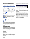
Typical Job Cycle
In order for the system to run it must be in the active
state (status LED next to on the ADM is green).
Before a job begins the automation controller outputs
should have the following values:
• Style Strobe: 0
• Dispense Complete: 0
• Dispense Valve x On: all should be 0
• Style: Any value is acceptable
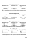
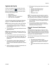
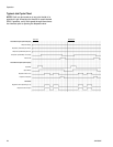
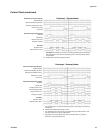
A typical job cycle consists of the following dispensing
sequence. See Typical Job Cycle Chart, page 50.
NOTE: Each job cycle can apply to only one fluid plate.
1. The automation controller checks that Dispenser
(Fluid Plate) Ready signal is set to 1. If it is set to 1,
a job can begin.
2. The automation controller sets the Style to the next
desired style value.
NOTE: Each fluid plate has a unique set of styles. For
example, Style 2 for Fluid Plate 1 is different from Style
2 for Fluid Plate 2.
3. The automation controller sets the Style Strobe to 1.
4. PCF reads the Style bits to select the new style. The
system then starts a new job and sets Dispense In
Process to 1.
5. The automation controller begins dispensing. The
automation controller sets and clears Dispense
Valve x On bits as desired throughout the course of
the job.
6. When the dispense is complete the automation con-
troller sets Dispense Complete to 1.
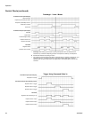
7. PCF sets the following signals based on the results
of the job.
• Dispenser (Fluid Plate) No Alarm
• Dispenser (Fluid Plate) No Error
• Dispense Volume OK
•Error
• Dispensed Volume
NOTE: The automation controller should not read the
Dispense Volume OK or Dispense Volume signals until
after the system clears the Dispense In Process signal.
8. PCF sets Dispense In Process to 0 to indicate the
job is complete. At this time the signals from step 7
should be read.
9. The automation controller must clear Dispense
Complete and Style Strobe (either can be cleared
first) before the next job can start.
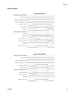
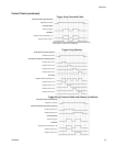
Jobs with Command Cable Dispense
Trigger
With the Dispense Trigger Source configured to Com-
mand Cable or Command Cable 3x, users only need to
trigger the dispense applicator to start a job. This config-
uration is useful for less demanding applications that do
not require a full automation interface.
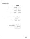
The following limitations apply when starting a job with
this configuration:
• The selected style defaults to Style 1.
• There can be up to a 100 ms delay before dis-
pensing while PCF prepares for the new job
cycle.
• The job end mode timer must be used to end a
job.